Jump to content


Photo

DIY Change Your Steering Rack


  • Please log in to reply
14 replies to this topic

#1 daggles

daggles

    Super Member

  • PipPip
  • 300 posts
  • Gender:Male
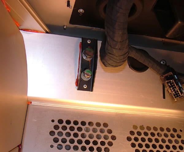
  • Location:St. Neots, Cambs.

Posted 31 August 2008 - 06:15 PM

There are lots of snippets of info about how to change a rack and most accounts seem to suggest lots of wriggling and swearing is required but that it’s much easier next time. If you are only intending to do this once, I thought I’d save you the trial and error bit (and pain) and tell you how I did it. Vauxhall think parts of this takes 2 people - maybe that’s why they charge so much - but I did this on my own in a few hours and that includes tea and DIY tracking adjustment. I’m not saying this is the best / right way to do it and there is a lot of detail here so if you think I missed a bit maybe I did, so please use your own common sense if any of this looks dumb.

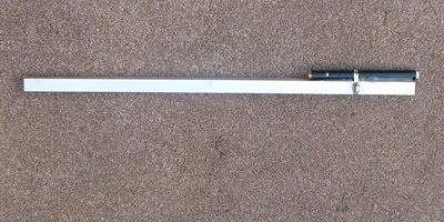
If you are happy with your existing tracking setup you might want to make this little device first which I guarantee will save you time and the cost of having your tracking checked afterwards.
Posted Image

Pop onto eBay and buy one of those cheap laser pointers, you should manage that for under a fiver. Then get yourself something rigid to mount it on, I used a bit of U-channel aluminium from B&Q. Cut the channel to length (I’m assuming you went for the same as me) so it spans the rim of a front wheel.

Put the pointer on top of the channel and make sure that the beam is roughly parallel to the channel, no need to be too accurate – the beam usually comes out of the pointer at a slight angle so rotating the pointer is an easy way to make the adjustment. Strap the pointer firmly to the channel with something like tywraps or jubilee clips, it’s crucial that nothing moves when you start using it so I used hot melt glue just to make sure. Arrange for the laser to stay on, I did this by just pushing the button in and forwards until it stuck on then you can unscrew the battery cap at the bottom to turn it on and off.

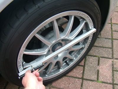
To record your current wheel alignment, park your car about 20 feet from a wall or garage door at a right angle – the further back the more accurate the measurement will but I reckon 15+ feet is fine, with the wheels straight ahead. Mark the ground with the position of one of the wheels so you can put the car back to the same distance later. Put the channel on the first wheel rim, hold it horizontal and level with the wheel centre.
Posted Image

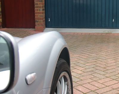
Have an accomplice mark the point on the wall / door where the spot lands then do the same with the other wheel.
Posted Image

That’s it, when you have finished with the rack, you can put the car back in the same place and when your wheel alignment is correct your dots will be the same distance apart as your marks.

Things you’ll need to swap the rack
An inspection lamp / torch
13mm & 17mm sockets
Molegrips
2x 13mm spanners (or one and the socket)
X, x and x Open ended spanners
A large flat screwdriver
2x smallish flat or Phillips screwdrivers
A hammer
A Jack
Your wheel key and wheelnut spanner
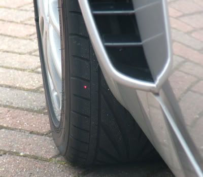
Sticky tap
2 new Nylock nuts for the track-rod ends
2 new 13mm Nylock nuts for the intermediate shaft bolts (or not depending on what sort of fixing you find)
2 Plastic carrier bags
4 bits of cardboard about 10" square
Washing up liquid
Radox Muscle Soak Herbal Bath
Tea

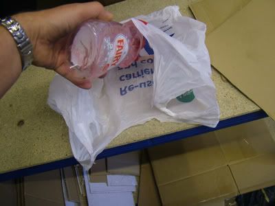
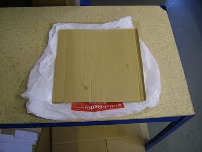
Before you start make a couple of these to make moving the wheels easier. Get a nice thick plastic carrier bag, M&S ideally, Tesco as a last resort. Sprinkle some washing up liquid inside the bag
Posted Image

Sandwich the bag between 2 bits of cardboard, then make another one exactly the same. Put one under each front wheel and a 2 year old will be able to turn the steering wheel with the car stationary.
Posted Image


1. Put the handbrake on

2. Turn the steering wheel fully clockwise

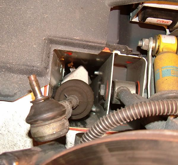
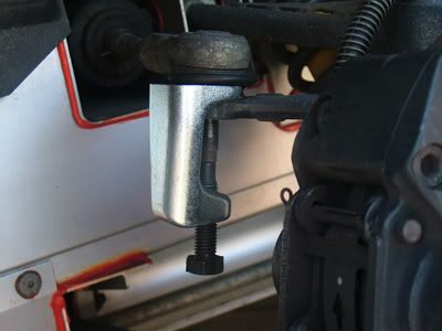
3. Look in the LH wheel arch, you can see the track-rod end easily enough. Undo the nut with a 17mm socket. Tap (don’t bang) the track rod end from underneath with a hammer and it should pop out. If you are swearing already one of 2 things has happened.. either the track rod end came loose early and the nut is just rotating the threaded portion, in this case clamp the track-rod end to the arm with a pair of Molegrips, now you’ll be able to undo the nut... or... tapping was fun but the track-rod end didn’t come out. If this was a Mondeo you would be going to look for a bigger hammer about now, but resist. Use a splitter if you have one or go and buy the cheap screw based splitter from Halfords (pictured below) for £7.99 if you don’t.
Posted Image

4. Jack the RH side of the car up and remove the front wheel.

5. Undo the Track-rod end nut and separate the joint as in 1.

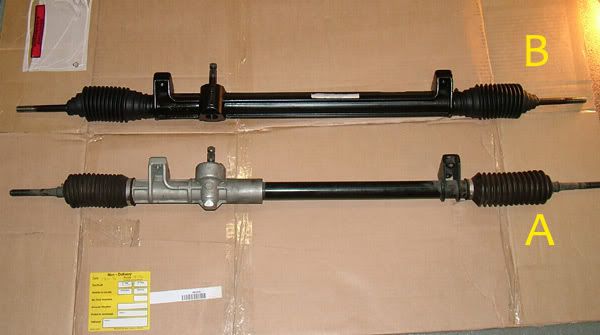
6. Take a look in the rack tunnel and see which of these 2 racks you have. a. Rack 'A' will come straight out with no problems at all as the casing under the spigot is narrower. With rack 'B' you might be lucky but most likely you’ll spend ½ an hour twisting and swearing and it will still be in there, so..
Posted Image

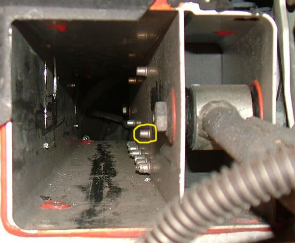
if you have rack 'B' locate the Rivnut circled in the pic below, place the end of your large flat screwdriver at the base and whack the screwdriver with the hammer. The Rivnut isn’t used and as there is no bolt inside it, a couple of decent clouts will snap it off. This will give you plenty of room to extract the rack.
Posted Image

7. Take your 13mm and 17 sockets and the pair of 13mm spanners, sit in the driver’s seat with your legs out of the door and lean under the dash.

8. Marvel at how neatly the handbrake handle fits between your 2nd and 3rd ribs

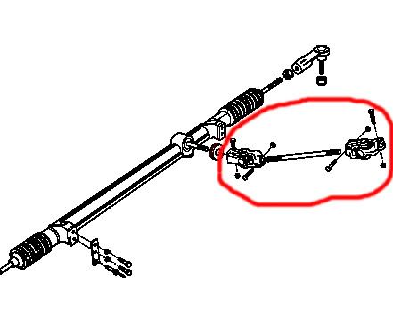
9. Using your 2x 13mm spanners, remove the bolts from the intermediate shaft universal joint(s) between the rack and the steering column. There are 2 types of shaft around, one with 2 joints and a separate shaft like this
Posted Image

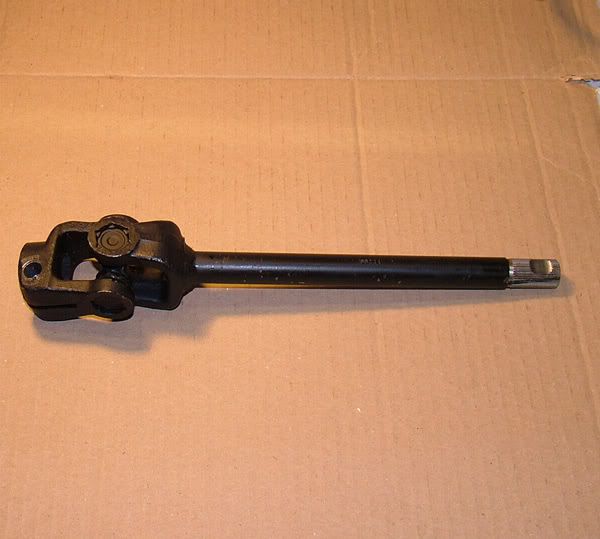
and 1 which has one joint welded to one of the UJ’s as in the pic below, so just remove as many bolts as you come across.
Posted Image

10. Don’t try and get the shaft out yet.

Hit my image limit here so see the next part for the rest...

#2 daggles

daggles

    Super Member

  • PipPip
  • 300 posts
  • Gender:Male
  • Location:St. Neots, Cambs.

Posted 31 August 2008 - 06:17 PM

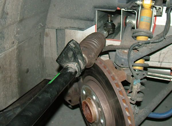
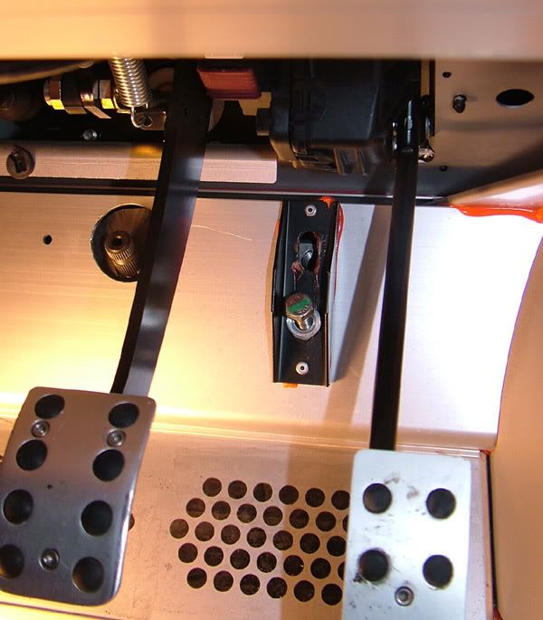
11. The rack is bolted to the floor through a couple of black steel brackets, one on each side. The bottom bolt is 13mm, the top is 17mm. Take out both bolts on both sides.

Posted Image

12. Pull the intermediate shaft upwards on it’s splines towards the steering wheel and it will slide off the rack spigot, the rack will flop back into the tunnel.
The intermediate shaft UJ's seem to be of pretty poor quality so while you have the one or more joints off it's well worth checking them. Clamp one end in a vice and twist the other end with a pair of Molegrips and you will probably find some slack. The end of the handle of a large pair of Molegrips is not far of the radius of the steering wheel rim so it will give you a good idea of how much play the joints are contributing at the steering wheel. Some new ones aren't that great either, I ended up sending some new replacements back and using a pair I got from a scrappy as they turned out to be the best I'd come across.

13. From the RH wheel arch look up the rack tunnel. Twist the rack until the spigot clears the hole in the floor and pull the rack out .

Posted Image

14. If you didn’t knock out the Rivnut in step 6. earlier do it now as it makes putting the rack back easier later.

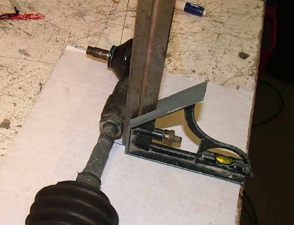
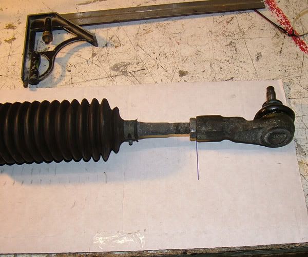
15. Lay the rack on something long and flat that you can draw on such as a sheet of cardboard. Find something to use as a square and line it up with the edge of the track-rod straight down to the cardboard . Mark a line on the cardboard then do the same at the other end.

Posted Image

Posted Image

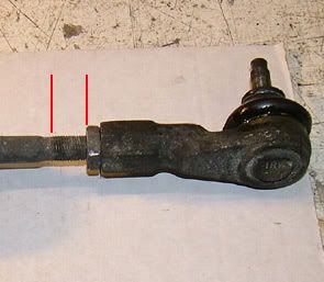
16. Make a note of how many threads are showing past each of the lock nuts and add the numbers together - unless you’ve been using one of those brain trainers, write the number on the cardboard.

Posted Image

17. Slacken the lock nuts and remove both track-rod ends

18. Screw both the lock nuts onto the new rack leaving ½ the total number of threads you calculated earlier showing.

19. Screw both the track-rod ends onto the new rack until they reach the lock nuts

20. Lay the rack on the cardboard and using your square line up one track-rod end against the line you drew earlier. Check the other end to see how far out you are.

21. By screwing both track-rod ends – not just one - make any adjustments you need until the track rod ends match up to the lines.

22. Tighten the lock-nuts. At this point there are lots of tips around for finding the centre of the rack, marking the spigot etc. none of which are any use once the rack is in the car unless you have a spring for neck so forget about it.

23. Move the rubber gasket from around the spigot of the old rack to the new one.


Half done, good time for a cuppa...


24. Lay the rack in the orientation it will be in the car and twist the track-rod ends so they point vertically upwards, this stops them snagging on things when putting the rack back in.

Posted Image

25. Slide the rack into the channel until the spigot lines up with the hole and twist the rack until the spigot drops into the hole. Some help is handy here but if you want to prove you are worth 2 Vauxhall technicians carry on..

26. Starting on the left hand side, take your 2x small screwdrivers and crawl back under the dash.

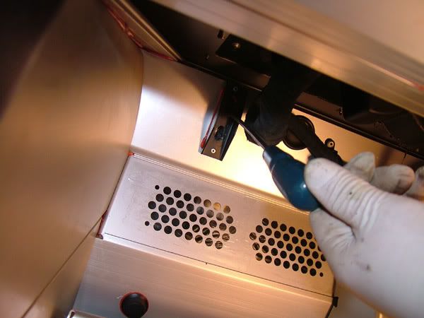
27. Use the 2x small screwdrivers through the bolt holes to lift the rack up until you can get one screwdriver to locate the top hole in the rack through the top hole in the floor.

28. Put the 13mm bolt in the bottom and tighten it gently, then screw the 17mm top bolt in a few turns

Posted Image

29. The RH side will be easier as the rack is pulled square to the tunnel by the bolt on the LH side. Put both bolts in a few turns the go back to the left hand side and slacken the bottom bolt again until it is only holding by a few threads. What you have now is the rack fairly loose in the tunnel (you’ll need that slack a bit later) but all of the bolts are in.

Posted Image

30. Go round to the RH side, put the Track-rod end back into the arm and tighten the (new) Nylock nut to 30Nm. If the end rotates and the nut doesn’t tighten use the mole grips to press the Track-rod end into the arm while you tighten the nut

31. Push the wheel round to the right.

32. Go to the LH side and refit the track-rod end as above.

33. Put the RH wheel back on and let the jack down.

34. The next thing to do is to get the wheels pointing straight ahead. Lots of ways to be inventive with string and small blocks of wood here but if you made the laser tool at the start it’s simple, just use it pointing backwards and it should hit the rear tyre.

Just turn the steering wheel until the dot hits the tyre at the same place on both sides and you are done.

Posted Image

35. Sit in the car and centre the steering wheel (not on the p**s as in the pic below). Hold it still with your knees and stick some tape round the rear of the wheel to the cowling. About 10” tape properly stuck will keep the wheel nicely clamped in the right place.

Posted Image

36. Back under the dash. If the various UJ’s and intermediate shaft have dropped off after you took the bolts out, put them back to together. There are flats on the intermediate shaft so the bolt holes in the UJ’s have to be aligned with the flats before the bolts will go in. Put all the bolts in but don’t put the nuts on.

37. Engage the bottom of the intermediate shaft on the steering column spigot. If you need more room, take the bolts out of the UJ’s and they will slide up the splines on the intermediate shaft. If that still doesn't give you enough room, take the instrument binnacle out and release the 3 bolts holding the the steering column mounting bracket.

38. Tighten all 4 rack bolts – 22.5Nm for the bottom ones, 45Nm for the top. (I suspect there ought to be some threadlock involved here? but mine didn't have any)

39. Check that you have the regulation 1 1/4 turns each side of centre on the steering wheel

40. Put the bolts back into the intermediate shaft and tighten the nuts.

41. I seem to recall that Vauxhall think no job is complete without putting the roof on as the final step, so if you think it might improve the steering that little bit more then go for it..
Time for more tea..

Now for the tracking adjustment

1. Put the car back where you made your initial measurement and make sure you have you carrier back thingies (see things you'll need back at the start) under the front wheels.

2. Wind the drivers window down so you can reach the steering wheel

3. Hold your laser tool on the RH front wheel and turn the steering wheel until you hit your original mark

4. Go to the LH side, hold your laser tool on the wheel and see how far you are off hitting your original mark you are. If you were careful counting the threads etc. earlier, at 20 feet distance you should find you are within 2 - 3 inches.

5. If you need to make an adjustment start with the RH side. Turn the steering wheel to the left until you can see the RH Track-rod end. Slacken the lock nut.

6. Use a spanner on the flat part of the Track-rod to rotate it and push the Track-rod end in or out as required. Clockwise as you look at the Track-rod from the Track-rod end will move the front of the wheel in towards the centre of the car and reduce the distance between your dots. Don't forget you only need to make half the adjustment you need on this side as you will need to make the same adjustment on the other side to maintain the central position of the steering wheel. From memory I reckon half a turn each side is worth about an 1 1/2 inches between the dots.

7. Repeat the check and adjustments until your dots are bang on the distance apart that you had at the start.

8. Jump in the car and drive backwards and forwards about 10 feet until you are happy you are driving in a straight line then look at the steering wheel alignment. If it's a tad out make small adjustments of both Track-rods (in opposite directions) to centre the wheel. 1/4 of a turn on the Track-rods is about the equivalent to 5 mins (using a clock reference) of rotation of the steering wheel

9. Do a quick check that your tracking is still ok then tighten the Track-rod end lock nuts
Well that’s about it. If all went to plan that should have taken about 4 hours including the tea breaks and you can allow yourself a broad grin when you think about how much money you haven't given to Vauxhall and the local tyre depot.

Now go and sit down for 10 mins, when you try and get up again you will figure out why Radox Muscle Soak Herbal Bath was on the things you need list, or maybe that's just my age...

#3 techieboy

techieboy

    Supercharger of Doom

  • 22,914 posts
  • Gender:Male
  • Location:Bedford

Posted 31 August 2008 - 07:13 PM

Now go and sit down for 10 mins, when you try and get up again you will figure out why Radox Muscle Soak Herbal Bath was on the things you need list, or maybe that's just my age...


Ah, missed that bit on the original guide but it's definitely a required part of the job. I'm hobbling around at the moment with muscles I didn't even know existed, screaming in pain at having been woken from their long slumber.

Thanks for the earlier tips and making the guide public - just wish I'd seen it before I started.

Definitely one for the "Useful Threads Collection".

#4 petrolhead1

petrolhead1

    Need to get Out More

  • PipPipPipPip
  • 936 posts
  • Gender:Male
  • Location:Wantage, Oxfordhsire
  • Interests:Windsurfing and Sailing
    Karting
    My family

Posted 31 August 2008 - 09:48 PM

Now go and sit down for 10 mins, when you try and get up again you will figure out why Radox Muscle Soak Herbal Bath was on the things you need list, or maybe that's just my age...


Ah, missed that bit on the original guide but it's definitely a required part of the job. I'm hobbling around at the moment with muscles I didn't even know existed, screaming in pain at having been woken from their long slumber.

Thanks for the earlier tips and making the guide public - just wish I'd seen it before I started.

Definitely one for the "Useful Threads Collection".

:yeahthat: Mods come on wake up. Put it in there!!

#5 snoopstah

snoopstah

    Scary Internerd

  • PipPipPipPipPipPip
  • 3,056 posts
  • Gender:Male
  • Location:Vancouver, BC

Posted 01 September 2008 - 02:40 PM

What a freakin' awesome guide! Imnotworthy Need more info about that dash too though - what's the centre dial?

#6 Arno

Arno

    Need to get Out More

  • PipPipPipPip
  • 1,237 posts
  • Gender:Male
  • Location:Netherlands

Posted 01 September 2008 - 04:14 PM

Before fitting a new or reconditioned 'B' style rack you should also check the preload on the pinion gear. (not sure if the 'A' type can be adjusted) The rack should require a force of 12-16 lbf (50-70N) to move it by pulling on one track rod in a smooth and constand movement from one end to the other. By loosening the locknut on the back of the housing you can adjust the threaded plug that presses a thust pad onto the rack bar and pinion gear, so you can adjust the 'stiffness' of the rack to the correct tolerances. Usually they are miles out when delivered new... Bye, Arno.

#7 techieboy

techieboy

    Supercharger of Doom

  • 22,914 posts
  • Gender:Male
  • Location:Bedford

Posted 01 September 2008 - 05:06 PM

Usually they are miles out when delivered new...


:o

Fcuk that! There's now way this bitch is coming back out again any time soon. Whether the pre-load is correct, or not, it feels hugely better than my 7 year old original rack. Hadn't realised, until this exercise, just how sloppy the steering was (still felt massively more accurate and communicative than a regular car). Quite amazing how we just don't notice gradual changes in steering/suspension response and subconsciously ignore those changes.

Not sure whether it's the rack on it's own or in combination with the new revised raiser plates but the bump steer is hugely improved on some of the lumpy roads around here. I had to take the car home after 1.5 miles of test driving just to recheck everything was in place as it all felt so different.

Can't wait to do the suspension overhaul/refresh in the winter now. Anti-roll bar bushes felt a bit more spongy than I expected so they're next along with the drop links - although I think I might bite the bullet and upgrade the anti-roll bar to the Elise Parts adjustable one

#8 daggles

daggles

    Super Member

  • PipPip
  • 300 posts
  • Gender:Male
  • Location:St. Neots, Cambs.

Posted 02 September 2008 - 08:40 PM

What a freakin' awesome guide! Imnotworthy

Need more info about that dash too though - what's the centre dial?


It's a boost guage..

Posted Image

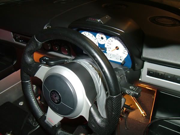
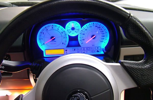
It's a long story but the rev counter in my stack croaked. After a lot of agro trying to get if fixed (without success) I tried a more creative route...

I took the board off the back of the stack and made some spacers to mount it 2 inches further back. Then I got a cheapy rev counter from ebay, hooked it up to the input plug on the stack and it worked fine. So rather than just put it all together in standard format I made a new dash layout. The speedo and rev counter needles are shortened by about 15mm and the diameter of the faces are smaller. This leaves enough room for an extra dial and an extra LCD temp guage for later use with a chargecooler. The small knob on the lower right selects any one of 3 thermocouple inputs to the temp guage. I needed to add extension cables for the speedo stepper motor, lighting LEDS and original LCD display.

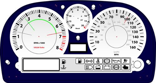
The new background card I knocked up in Adobe Illustrator, printed it on card and gave it a coat of sticky backed plastic. Got a piece of acrylic sheet and sprayed a new mask on it. This is a closer view of the design with mask (its offset cos you look at it at an angle)..

Posted Image

I changed the lights to blue for good measure and bobs your uncle. Oh and I moved the shift light to the top of the binnacle so it shows up in the screen as a head-up (brilliant).

Yes I did do it in the winter when the nights are long an cold and a VX is just for looking at in the garage.

#9 Sambo1

Sambo1

    Super Member

  • PipPip
  • 478 posts
  • Gender:Male
  • Location:Camberley

Posted 02 September 2008 - 10:17 PM

That is fantastic Imnotworthy

#10 daggles

daggles

    Super Member

  • PipPip
  • 300 posts
  • Gender:Male
  • Location:St. Neots, Cambs.

Posted 30 December 2008 - 11:20 AM

A note on the wheel alignment: You need to make sure the wheels are pointing striaght ahead (accurately) when you measure the distance to begin with and again when you are setting the tracking. Goto the section that talks about centreing the steering wheel for a note on how to get the wheels pointing straight ahead.

#11 willis

willis

    Member

  • Pip
  • 107 posts
  • Gender:Male
  • Location:south wales
  • Interests:fast cars bikes and friendly birds

Posted 29 March 2009 - 06:47 PM

A note on the wheel alignment: You need to make sure the wheels are pointing striaght ahead (accurately) when you measure the distance to begin with and again when you are setting the tracking. Goto the section that talks about centreing the steering wheel for a note on how to get the wheels pointing straight ahead.

how much is a rack and were is the best place for me to get one mine has play in it

#12 mandarinvx

mandarinvx

    King of First Replies

  • PipPipPipPipPipPipPipPip
  • 12,621 posts
  • Gender:Male
  • Location:West Mids / Oxfordshire

Posted 29 March 2009 - 08:06 PM

Titan Motorsport can provide a replacement (about £250 I think :unsure:) They also offer a refurb service thumbsup

#13 theolodian

theolodian

    Recovering VX owner

  • PipPipPipPipPipPip
  • 3,195 posts
  • Gender:Male
  • Location:Coventry

Posted 30 May 2009 - 04:24 PM

On my 01 NA that riv nut holds the top bracket for the heater assembly. Banged it out anyway. :rolleyes: Thanks for saving me tons of hassle. thumbsup

#14 MrGman

MrGman

    Super Duper Member

  • PipPipPip
  • 735 posts
  • Gender:Male
  • Location:Crowborough

Posted 17 November 2012 - 08:09 PM

I've been doing my rack today so thought i'd post a few things just to update the guide. The racks are still available from Titan, http://www.titan.uk....tent.aspx?id=44 They offer the two version still, the OEM 2.75 turns lock to lock and the slightly quicker 2.5turns lock to lock, the prices have gone up, the OEM rack is around £300+vat and the 2.5 is around £322+vat Very helpful on the phone too. When doing the rack i thought i'd replace the uj's at the same time, I followed the guide above and it was all straight forward until it came to connecting the uj's and intermediate bar up. I bought the uj's from eliseparts and got one of the two piece kits, with this there wasn't enough room for me to reconnect the uj's so i had to make more play by loosening the steering column, this is done by removing the dash top, binnacle and instrument panel, once these are removed you'll see a 13mm bolt and two 10mm bolts going through a gold bracket on the steering column, if you remove the 13mm bolt completely you'll be able to pull the wheel and column back enough to gain access to the top uj, once that is replaced put it back through the hole and put the 13mm in a few turns. If you leave this loose you'll have a few more mm of play in the uj's/intermediate bar to connect them all back up. Once it's all done i'd suggest checking the wheel is straight before putting it all back together as if the wheel is off centre you'll need to take it all apart again.

#15 Dunk

Dunk

    Need to get Out More

  • PipPipPipPip
  • 1,224 posts
  • Gender:Male
  • Location:Edinburgh
  • Interests:WLTM reliable, quiet, tidy one for LTR.

Posted 18 November 2012 - 09:34 AM


It's a boost guage..

Posted Image

It's a long story but the rev counter in my stack croaked. After a lot of agro trying to get if fixed (without success) I tried a more creative route...

I took the board off the back of the stack and made some spacers to mount it 2 inches further back. Then I got a cheapy rev counter from ebay, hooked it up to the input plug on the stack and it worked fine. So rather than just put it all together in standard format I made a new dash layout. The speedo and rev counter needles are shortened by about 15mm and the diameter of the faces are smaller. This leaves enough room for an extra dial and an extra LCD temp guage for later use with a chargecooler. The small knob on the lower right selects any one of 3 thermocouple inputs to the temp guage. I needed to add extension cables for the speedo stepper motor, lighting LEDS and original LCD display.

The new background card I knocked up in Adobe Illustrator, printed it on card and gave it a coat of sticky backed plastic. Got a piece of acrylic sheet and sprayed a new mask on it. This is a closer view of the design with mask (its offset cos you look at it at an angle)..

Posted Image

I changed the lights to blue for good measure and bobs your uncle. Oh and I moved the shift light to the top of the binnacle so it shows up in the screen as a head-up (brilliant).

Yes I did do it in the winter when the nights are long an cold and a VX is just for looking at in the garage.


This is easily the nicest interior modification I've ever seen on a VX. Well done that man. Imnotworthy


1 user(s) are reading this topic

0 members, 1 guests, 0 anonymous users