Jump to content


Photo

My 2-Day Sc Conversion


  • Please log in to reply
82 replies to this topic

#1 smiley

smiley

    Thetan level 15

  • PipPipPipPipPipPipPip
  • 10,427 posts
  • Gender:Male
  • Location:Netherlands

Posted 08 November 2011 - 10:13 PM

Earlier this year i built in my SC together with exmantaa and speedster4fun from the NL club (also members here).
As i am technically challanged, my main job was making coffee and taking pictures.
It was done in 2 (very long) days.


Day 1; The cooling and the hosework:

First step is of course the front clam off.
Also took the opportunity to put maze over the air inlets in the crash box
Posted Image

Then bleed the radiator, and take it out, as it was OEM, thus a ticking timebomb.
The radiator is only screwed to the radiator housing. When all screws are loose, they come off the crashbox at the same time

Posted Image
The new elise-shop radiator is bolted on top of the pro alloy radiator. Some small strips of plastic are put between the the 2 to make sure the warm normal radiator does not affect the SC one.

The existing fan plug is cut off the original fan for reuse.
The 2 new smaller fans (that belong to the pro alloy kitt) take over the task of the larger old one.
The old fan plug is connected to both connectors on the new fans. All put together:
Posted Image

In order to test the fans if they work you can activate them by putting a small set of plyers on the 2 thick wires from the second relay, which should cause the fans to spin.
Posted Image

Put something light on the radiator. If it blows up, the electrics are ok. If not, you need to swap the wires on your plug.

Posted Image
I had the cooler version with pipes on the drivers side (euro). So 2 holes need to be made in the radiator housing.
The whole shabang is then ready to be put back in, but not just yet as we need all the room there is for the hoses part.

There are 2 methods to get the hoses in. First the method we used:
Saw a temporary hatch in the inside of the sill:
Posted Image

Pay attention not to stick the saw part in too deep, as important hoses allready go through there.
Posted Image

The white color you see, is the first foam layer to penetrate.
For this we created a pipe with teeth that fits exactly in a vacuum machine pipe.
Posted Image

Posted Image
This way you can easily turn it around, and saw out the exact circle you need (the foam is about 4cm wide, and very soft)

Posted Image
In the background you can see an identical foam layer (also 4 cm to go through).
Keep in mind that the chassis is smaller in the front then the back, so keep the pipe in line with it, to make sure you end up correctly in the back.

#2 smiley

smiley

    Thetan level 15

  • PipPipPipPipPipPipPip
  • 10,427 posts
  • Gender:Male
  • Location:Netherlands

Posted 08 November 2011 - 10:14 PM

The hose can now be fed through the pipe to the back:
Posted Image
In the top of the sill 2 holes are made for the hoses to pass through.
They sort of make an S shape inside the sill, before going to the back.

When you take off your left back wheel and liner you can stick your head in, and you will see a black piece of foam: (pretty big and thick)
Posted Image
The trick is to end up under the foam block with the hoses.

Posted Image
Your 2 hoses can now take the same route as the other hose into the engine bay.


Posted Image
The hoses are equiped with rubber rings, so they will not sand against the sill.

Posted Image
The first hose will now be roughly at the hight of your abs computer, and the second one will be in the wheel arch.
I put some foam on the hose to make sure it would not rattle against the clam.
Posted Image


Another method to get the hoses in, is to remove the sillcover. (the black piece with the triangles)
You then get room to stick your hand in, and try to route the hose that way.
You probbaly need to break through the white foam pieces with your hoses, and it will be quite a puzzle to get them under the black foam part.

Will post the good stuff tomorrow evening.

Edited by smiley, 08 November 2011 - 10:16 PM.


#3 techieboy

techieboy

    Supercharger of Doom

  • 22,914 posts
  • Gender:Male
  • Location:Bedford

Posted 08 November 2011 - 10:20 PM

Fantastic method of running those hoses. Imnotworthy Though I'm not sure I could have ever taken a jigsaw to the end of sill, like that. :o

#4 Mike (Cliffie)

Mike (Cliffie)

    Back in a VX

  • PipPipPipPipPipPipPipPip
  • 13,353 posts
  • Gender:Male
  • Location:North Yorkshire
  • Interests:Weaving weasels woolly hats.

Posted 08 November 2011 - 10:23 PM

Track day at Assen or Zandvoort anybody?

#5 VXT Tim

VXT Tim

    No it's not a Lamborghini!

  • PipPipPipPipPipPipPip
  • 11,421 posts
  • Gender:Male
  • Location:Derby

Posted 08 November 2011 - 10:24 PM

I'd love to do Assen. Good write up so far.

#6 Nelly Vx

Nelly Vx

    3/3 Of a Queen

  • PipPipPipPipPipPip
  • 5,928 posts
  • Gender:Male
  • Location:north wales

Posted 08 November 2011 - 10:31 PM

Looking forward to the updates Imnotworthy chinky chinky

#7 jonnyboy

jonnyboy

    The hardtop guy

  • PipPipPipPipPipPipPip
  • 8,290 posts
  • Gender:Male
  • Interests:Lightweight sportscars, Brunettes, Petrol & Beer.

Posted 08 November 2011 - 10:37 PM

Love the cutting method with the pole. Genius!

#8 smiley

smiley

    Thetan level 15

  • PipPipPipPipPipPipPip
  • 10,427 posts
  • Gender:Male
  • Location:Netherlands

Posted 08 November 2011 - 11:21 PM

Day 2, time for the good stuff :lol:

The boot lid, rear wheels and arches come off.
Posted Image
The clam is protected with bubble wrap, as you will be leaning against it a lot.

Remove the airbox, airpipe, throttle body and inlet manifold. Then disconnect the fuel rail:
Posted Image
Try to drain as much coolant as possible before disconnecting the cooling hoses as this is really nasty stuff to clean up.

I mounted the pro allow catchtank on the same bracket as where your normal header tank is mounted on.
It's a perfect fit, as it was custom designed for the vx (as was the radiator).

Posted Image
On the left you see the relais, and on the right the bosh pump.

For the pump you need 3 wires; a continuos power, an earth wire and a signal wire.
For the signal wire we took the one for the fuel pump relais, which on my car was the white/purple wire on the blue connector block part.
Posted Image
Do not go blind on the color; This wire is pin number 8 on te blue X2 connector.

The continous power was taken from the starter motor:
Posted Image

The earth can be taken from the central earth connector on the engine block:
Posted Image

The stock water cooling hose is in the way of where the SC pully needs to be, so needs to be re-routed.
You can go over the SC, or around it. We went around it (that's the S hose courtenay sells).
Posted Image

The S hose is mounted here, with an alloy spacer in between the S and the stock one:
Posted Image

The bottom bracket for the SC can now be mounted on the engine.
Posted Image
Some do not put it in, as it's a pita to reach, but as the manifold plus SC is quite heavy, i did not want to have the weight put on the inlet bolts alone, so we put it in.

#9 smiley

smiley

    Thetan level 15

  • PipPipPipPipPipPipPip
  • 10,427 posts
  • Gender:Male
  • Location:Netherlands

Posted 08 November 2011 - 11:23 PM

The manifold can now be put on, also referred to as the laminova, due to the cooling type:
Posted Image
On the right side you can see 3 small pipes, on which the outer 2 are connected with a Y piece.
The inner one is to receive cooling water from the SC radiator, and the outer 2 go via the Y piece to the catchtank.
This Y piece setup is referred to as the dual pass modication.
By default it only has 2 pipes in it. (you need to send an original to courtenay for conversion)

So default has 2 pipes, which is of course 1 for water in, and the other for water out.
That way the cooling water will pass through all 4 laminova cores, before it exits (quad pass; in from below, and out at above):
http://www.youtube.com/watch?v=s98OuoHAg8I
With 3 pipes, the water enters via the middle pipe, splits inside on the 2 laminova cores, and travels through the outside laminova's via the 2 exit pipes out.
The cooling water now become s less hot then with the quad pass, as it exits the system earlier.

The complete route of the cooling water:
Posted Image

Here you see the laminova cores, and the dual pass endplate (GM Part #88958721)
Posted Image
The laminova's can only send water one way, so make sure they are correct, in case you modify your quad pass to dual pass.

Here they are correctly set for dual pass:
Posted Image
Dual pass is only handy for track use, or stage 3 preparation. (this is a stage 2 conversion)

Of course the gasket goes on, before putting it on the engine:
Posted Image

The manifold bolted on:
Posted Image

Here you can see clearly how close the (modified) 100 amp dyno is to the manifold:
Posted Image
Trying to use a larger 120 apms is pretty much not going to work. Get your hands on a smaller 100a is best practice.

The black turbo injectors (max 270bhp) put in the fuelrail:
Posted Image

My fuel lines are cut, to be rerouted to the left, instead of the right.
Posted Image
The fule lines normally run on the right side, next to the engine, very much in the area of the SC belt, which can be dangerous if it snaps. (bending the lines out of the way of the SC belt as much as possible is also an option)
My lines are connected to the fuel filter, just behind the (euro) driver seat on the firewall.

#10 smiley

smiley

    Thetan level 15

  • PipPipPipPipPipPipPip
  • 10,427 posts
  • Gender:Male
  • Location:Netherlands

Posted 08 November 2011 - 11:24 PM

A new alloy bracket for the oil dipstick has been made:
Posted Image

The loom now has to be opened pretty much completely:
Posted Image
Make sure you number your injector wires before cutting!! (1,2,3 and 4).

The next wires need to be extended as the ecu will be mounted on the left side against the firewall:
4 x injectors (4 earth draden, for each of the injectors, and 4 x live wire which can all be put together, as the injectors are activated via the earth )
1 x map sensor (3 wires)
1 x ecap valve (2 wires)

Here are the new fuel hoses to be put on the rail later:
Posted Image


The pin layout of the throttle does not match the pin layout of the 68mm lsj throttle i have put on, and need to be adjusted:
Posted Image
With a small scredriver remove the purple protection cap

You can now see small black pins next to the coper colored connectors.
Move the small black pins to the side, and coper wires can be pulled out
Posted Image

Wire out:
Posted Image

The following wires need to be swapped:
Posted Image

The ecu is mounted on the left side of the firewall:
Posted Image

The loom can now be rebuild. (plastic protection tubing still missing here)
Posted Image

#11 smiley

smiley

    Thetan level 15

  • PipPipPipPipPipPipPip
  • 10,427 posts
  • Gender:Male
  • Location:Netherlands

Posted 08 November 2011 - 11:26 PM

The SC belt can now be put on. (In my case a "Continental Contitech 5 PK 1285")
The pully on the supercharger has been alligned 1.5mm to the outside to make sure it's alligned.
My 5 ribbon belt now runs on the left side of my 6 ribbon pully.
If you put he pully 1.5 mm to the inside, you cound run the belt on the outside ribes of the pully.

Without this, it's a matter of time before they start to squeek/shred.
Posted Image

You can now put on the last few hoses fuel lines, ecap valve and fuel regulator:
Posted Image

Car started first time, and perrrred like a kitten.

Went on the dyno a few weeks ago (still running the courtenay basemap)
Posted Image
(ignore the drag power part; it's a maha and spits out silly numbers on that part. The bhp and torque should be spot on)

Edited by smiley, 08 November 2011 - 11:27 PM.


#12 smiley

smiley

    Thetan level 15

  • PipPipPipPipPipPipPip
  • 10,427 posts
  • Gender:Male
  • Location:Netherlands

Posted 08 November 2011 - 11:45 PM

Engine bay fully finished

Posted Image

#13 ArticMonkey

ArticMonkey

    On the run from the grammar police!

  • PipPipPipPipPipPip
  • 4,792 posts
  • Gender:Male
  • Location:Essex

Posted 08 November 2011 - 11:53 PM

Great guide, and all with the clam on. Imnotworthy

#14 Rally

Rally

    Super Duper Member

  • PipPipPip
  • 650 posts
  • Gender:Male
  • Location:Staines-Upon-Thames

Posted 09 November 2011 - 12:01 AM

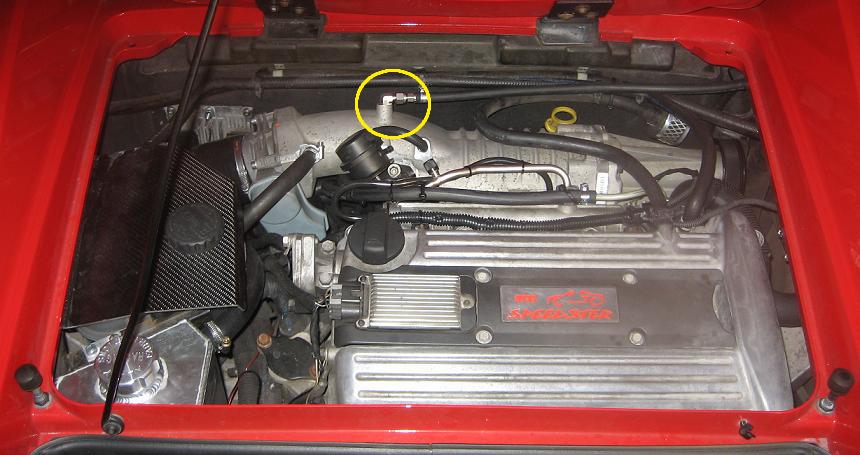
Smiley, great guide. A question about plumbing - there is a 90 degree adapter just behind the throttle body and a pipe running off to the right of the engine bay. What's going on there?

Edited by Rally, 09 November 2011 - 12:10 AM.


#15 smiley

smiley

    Thetan level 15

  • PipPipPipPipPipPipPip
  • 10,427 posts
  • Gender:Male
  • Location:Netherlands

Posted 09 November 2011 - 12:12 AM

Smiley, great guide. A question about plumbing - there is a 90 degree adapter just behind the throttle body and a pipe running off to the right of the engine bay. What's going on there?


That replaces the circled one on the 2.2 inlet manifold in the right picture:
Posted Image
The one with the square plug.

It's the fuel fumes recirculation if i'm not mistaking.
You can leave it out completely, but of course with more chance of fuel smell.

Edited by smiley, 09 November 2011 - 12:20 AM.


#16 smiley

smiley

    Thetan level 15

  • PipPipPipPipPipPipPip
  • 10,427 posts
  • Gender:Male
  • Location:Netherlands

Posted 09 November 2011 - 12:23 AM

Just noticed no pictures on the map sensor swap, but hope that's abvious. Also the throttle layout pin descriptions are in Dutch. If anybody needs it, it translate it into english. You will find more detailed guides on here then just my foto session. I just posted it as a visual aid to some large text based conversion descriptions out there.

#17 Rally

Rally

    Super Duper Member

  • PipPipPip
  • 650 posts
  • Gender:Male
  • Location:Staines-Upon-Thames

Posted 09 November 2011 - 12:26 AM

I've seen that a lot of conversions have that blanked off or have left the, presumably redundant, sensor in place. Is it optional to put that in?

#18 smiley

smiley

    Thetan level 15

  • PipPipPipPipPipPipPip
  • 10,427 posts
  • Gender:Male
  • Location:Netherlands

Posted 09 November 2011 - 12:28 AM

Is it optional to put that in?


Yes. Blanking off to get rid of the fumes is also fine.

Every country does things differently as you see :lol:

#19 Rally

Rally

    Super Duper Member

  • PipPipPip
  • 650 posts
  • Gender:Male
  • Location:Staines-Upon-Thames

Posted 09 November 2011 - 12:39 AM

Just to be clear, we're talking about this bit, right?

Posted Image

#20 smiley

smiley

    Thetan level 15

  • PipPipPipPipPipPipPip
  • 10,427 posts
  • Gender:Male
  • Location:Netherlands

Posted 09 November 2011 - 12:56 AM

Yes. chinky chinky


4 user(s) are reading this topic

0 members, 4 guests, 0 anonymous users