Honda K24 Powered Speedster
#321

Posted 06 July 2014 - 05:15 PM
#322

Posted 06 July 2014 - 05:49 PM
Number 9 is the stock ECU.
#323

Posted 06 July 2014 - 06:38 PM

#324

Posted 06 July 2014 - 06:42 PM
K24 start relay
pin 2 - negative
pin 3 - positive for starter motor solenoid
pin 4 - ignition switched positive
pin 5 - permanent positive
pin 6 - switched negative from start button
pin 9 - engine run signal from ECU
Edited by vocky, 06 July 2014 - 06:44 PM.
#325

Posted 06 July 2014 - 06:43 PM
Number 9 is the stock ECU.
...and number 2 is ground to the chassis rear
(Can somebody validate as I'm a noooooob when it comes to reading circuit diagrams ![]() )
)
EDIT: Vocky has just validated ![]()
Edited by Ormes, 06 July 2014 - 06:45 PM.
#326

Posted 06 July 2014 - 06:48 PM
you can also rewire it and use a normal relay, but the start button would always be enabled, so don't press it with the engine running ![]()
Use pin 4 and 6 for the relay coil (85 and 86) and 3 and 5 are the contact to be switched by the relay (30 and 87)
Edited by vocky, 06 July 2014 - 06:49 PM.
#327

Posted 06 July 2014 - 07:53 PM
I am not really following here Vocky. 4,6 and 3, 5 is what I have connected today. Must be something I must unplug or bridge or anything. Another question for you Vocky, on the big honda to VX Electric circut diagram on previous page. There is a wire number 16 from Engine harness connector (From start relay), is this something that doesn´t need to be plugged in or something that could/should be connected to VX starter relay? It feels strange not to have this connected as it is a thick Cable. :-) Thanks again. Peryou can also rewire it and use a normal relay, but the start button would always be enabled, so don't press it with the engine running
Use pin 4 and 6 for the relay coil (85 and 86) and 3 and 5 are the contact to be switched by the relay (30 and 87)
#328

Posted 07 July 2014 - 07:02 AM
I am not sure what the Honda starter motor requires, but on a z22se starter motor all it needs is a positive from the relay to energise the solenoid.
If you wire up a normal relay using the wires mentioned above the z22se starter motor will function.
Perhaps Arno might be able to help with the Honda starter motor wiring, I really need a Honda wiring diagram to help further.
#329

Posted 07 July 2014 - 07:46 AM
The Honda starter motor is conventional, so just a 12V solenoid feed to power/engage it just like the original starter motor.
The starter solenoid circuit on the Honda is normally wired via the C101 plug to the main engine harness with a thicker gauge black-white wire. This then connects to a small sub-harness on the front of the engine via a grey connector to interconnect the main engine harness to:
- Starter solenoid
- Knock sensor
- Alternator (stator power/alternator light)
The sub-harness also contains the main battery cable(s) that run from the alternator 12V and starter main 12V connection to the battery. This usually needs to be extended/modified to reach the power connections on these cars and also to remove the Honda ELD (Electric Load Detection) circuitry/logic (not needed if using a K-Pro'ed ECU)
Bye, Arno.
#331

Posted 12 July 2014 - 08:10 PM
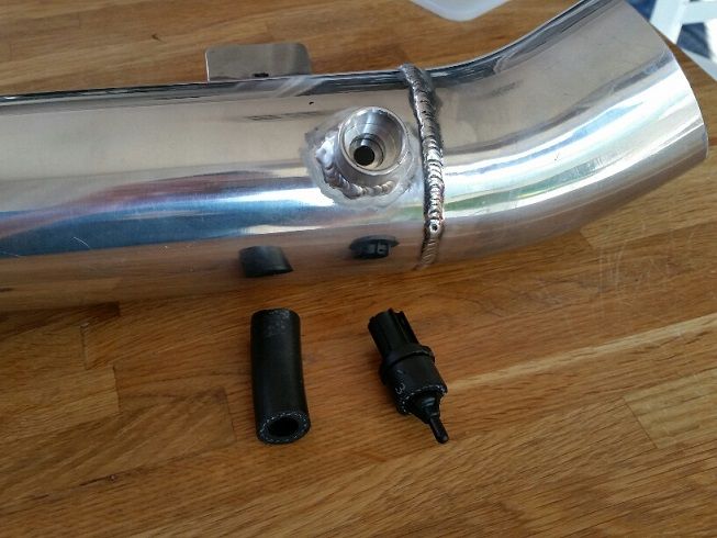
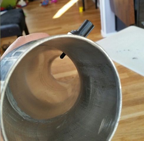
Should work fine this way. The NTC temperature element is pretty much the narrow tip of the sensor so as long as it's in the airflow it's OK.
Bye, Arno.
#332

Posted 13 July 2014 - 07:37 AM
The Honda starter motor is conventional, so just a 12V solenoid feed to power/engage it just like the original starter motor.
The starter solenoid circuit on the Honda is normally wired via the C101 plug to the main engine harness with a thicker gauge black-white wire. This then connects to a small sub-harness on the front of the engine via a grey connector to interconnect the main engine harness to:
- Starter solenoid
- Knock sensor
- Alternator (stator power/alternator light)
The sub-harness also contains the main battery cable(s) that run from the alternator 12V and starter main 12V connection to the battery. This usually needs to be extended/modified to reach the power connections on these cars and also to remove the Honda ELD (Electric Load Detection) circuitry/logic (not needed if using a K-Pro'ed ECU)
Bye, Arno.
so you can ignore that black/white cable and just use the vx220 wiring circuit instead ![]()
#333

Posted 15 July 2014 - 09:39 AM
#334

Posted 19 July 2014 - 05:18 PM
So Before we Went off to Denmark for a few Days I tried to fix my seat rails.
Had to cut the passenger seat mounts apart so I could Place them on drivet seat now when I have done my LHD conversion, the work did go smooth.
The result felt OK.

And I got the seat in, yay

But when moving the seat back to hindmost position I discovered the seat was touching the head rest, argh....
Never understood the purpose with the head rest really.

Having the seat in I asked my wife to help me bleed the brakes and clutch.
When bled the clutch I cheked the moving of the clutch slave cylinder.
I have a movement of about 18mm, anyone know if this is enough?
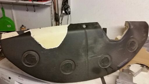
Today I started to adapt the dash panel to my LHD conversion. I made a template...
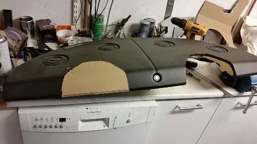
cutted it out, moved the left over piece to the opposite side and glued it.
Need som filler over it too.
When mounting aftermarket steering Wheel, which oem parts do I need to use?
This for example?

Over and out
, Per
#335

Posted 20 July 2014 - 07:58 AM
I used the Lotus Elise S1 set up on mine, so just the horn wiring goes to the steering wheel.
part 5 - http://www.deroure.c...&SMO=0&ST=&SC=0
Depending on which steering wheel you use you might have to modify the Lotus part.
So the black and white cable dont give any signal to the ECU?
from the info supplied by Arno, it's just a cable using the ecu plug but doesn't go to the ECU, so no signal to the ecu ![]()
#336

Posted 20 July 2014 - 12:45 PM
Yup.. The large grey 'C101' plug on the Honda engine harness is basically used to interconnect the engine harness to the 'car' or body harness in a Civic, just like the blue and black plugs on the VX220/Speedster (and EHC1+2 plugs on an Elise) connect to the rest of the car.
Some ECU signals get passed through C101 because the parts (eg. lambda sensor wires) are located further inside the car on a Civic and outside the engine harness itself, but the starter circuit works the other way around an just connects the ignition switch and relay to the engine harness (and via that to the small sub-harness on the front of the engine ![]() ). It does not connect to any of the square ECU plugs.
). It does not connect to any of the square ECU plugs.
BTW your clutch travel looks fine. You should be able to feel the definite pressure point when the clutch releases and the pressure plate spring tension gets less.
On the Elise it's sometimes required to put a stopper bolt under the clutch pedal as the clutch master cylinder is a little bigger than the one on a Civic and can cause over-extention on the clutch. But I think the VX/Speedster use a different MC (?), so once the car drives you'll just have to test and see if there's a lot of pedal travel left after the clutch has dis-engaged completely. Just add some sort of lower pedal stop if that's the case.
Bye, Arno.
#337

Posted 20 July 2014 - 12:55 PM
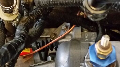
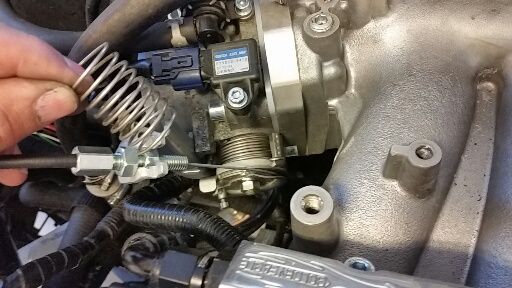
I was down in the garage this morning to try make the throttle pedal a bit softer.
I Removed the small spring. Only having the small spring makes me worried the throttle
won´t get back to rest position. SO I choose to use the big spring alone.
BR, Per
#338

Posted 20 July 2014 - 03:49 PM
#339

Posted 20 July 2014 - 08:12 PM
#340

Posted 24 July 2014 - 08:18 PM
the old fabric I can get it all off, there are still pieces of the old material.
Anyone having any super method of taking this away or cover this someway.

BR, Per
Edited by Aerodynamic, 24 July 2014 - 08:25 PM.
6 user(s) are reading this topic
0 members, 2 guests, 0 anonymous users
-
Bing (4)


