Honda K24 Powered Speedster
#481

Posted 19 March 2015 - 06:12 PM
#482

Posted 19 March 2015 - 06:20 PM
fezzasus, on 19 Mar 2015 - 3:50 PM, said:
I'm not sure I agree with the use of a brace bar, this subject has been explored in a great level of detail here and on lotus forums and no real conclusion has been drawn.
The use of the brace bar does reduce flex and therefore fatigue of the subframe, but damage from fatigue is very unlikely. This is more minimising the impact of the subframe flex on geometry of the car.
To counter the use of them, a brace bar will prevent shearing of the toe links in a collision, transmitting the force to the subframe and likely causing more damage.
I certainly would not say it is essential for track use.
Does this means you don´t use a brace bar?
Not doing this will save me some time so glad for this if it is not needed.
Anything else that needs to be thought of regardng track driving any other part of the subframe that needs to be reinforced? Uprated knuckle bolts and toe bar I have.
Br, Per
#483

Posted 19 March 2015 - 06:31 PM
The vast majority of people do not use brace bars.
I think there are a few differences between the turbo and NA subframes which strengthen the frame. Welding the frame to match the turbo may help.
#484

Posted 21 March 2015 - 10:30 AM
fezzasus, on 19 Mar 2015 - 6:31 PM, said:
The vast majority of people do not use brace bars.
I think there are a few differences between the turbo and NA subframes which strengthen the frame. Welding the frame to match the turbo may help.
Well, Then there is a renforcement done by Lotus then it must be to weak? Then I bracebar is something that could help
and the work I guess it´s more or less the same as making a bracebar.
I tryed to search for info how the Turbo subframe is reinforced without any luck. Anyone could share a Picture of explaine how and where it
is reinforced?
Br, Per
#486

Posted 21 March 2015 - 12:47 PM
Was just about to link that, just as well i checked Toms link 1st.
I can't see a brace bar hurting if you are using an NA subframe, it may stop it cracking in the future, but it does restrict you on exhaust routing.
#487

Posted 28 March 2015 - 07:01 PM
What are you guys who runs 9" rims in the rear do with the handbrake cabe? ´The handbrake cable will touch my inner side of the rim.
I could easy fix this with a plastic cabl tie, but I am afraid this will chafe off my control arm paint.
I was thinking of rerouting the Cable inside of the shock as an alternative but I thought someone have already done all this thinking before me,
so any suggestons?
Thanks in advance. Br, Per
#488

Posted 02 April 2015 - 12:42 PM
Anyone? Do you just take pasticstrip to tie in the handbrake cable or do you re route it?
Br, Per
#489

Posted 02 April 2015 - 01:02 PM
#491

#493

Posted 02 April 2015 - 04:40 PM
it's just heat shrink over the handbrake cable where it is cable tied, will try and get pictures but busy prepping clams for paint
#494

Posted 09 April 2015 - 08:26 AM
Arno, on 10 Oct 2014 - 3:56 PM, said:
The Rover blue sensor should have a resistance of: 100C - 75ohms, 0C - 2250ohms. So the second one you listed is closest and should already give reasonable values with the existing code and the voltage-dividing resistor in the circuit. Temperature range calibration is indeed 0°C to 160°C in the code for the picaxe. It varies the pulse-width between 0-100% as this is how the dash wants to receive the signal (100Hz pulse-width modulated signal) You can always test/calibrate the circuit for a different sensor by wiring it up and putting it in a cup of water with a thermometer and then slowly heat up the water and check the values and (if needed) correct the table in the code. Bye, Arno.
#495

Posted 09 April 2015 - 05:41 PM
Sounds normal.
As far as I know does the blue sensor indeed have 2 pins, but they are wired together internally and you need to measure between the thread/outside and one of the pins. Many automotive pressure and temperature sensors use the outside as the ground and use the engine block and chassis as the ground path back to the ECU/controller/whatever..
Value of 800 Ohms at room temperature doesn't sound too weird, but you can easily check the resistance values at 0C (drill a hole in a melting icecube and stick it in) and 100C (dip it in boiling water) to use as the calibration info for the controller. It takes some time for the sensor to reach the final resistance value at each temperature so look at the values on the multimeter and use the one it ends up stabilising at.
Bye, Arno.
#496

Posted 17 April 2015 - 07:53 PM
Time for a update, some work have been going on behind the scenes.
i
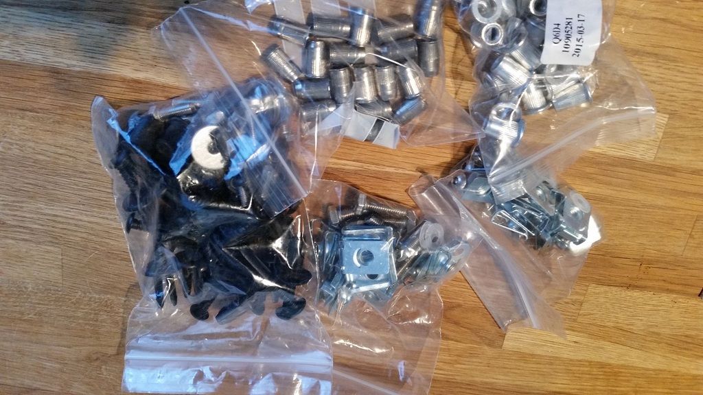
So first I figure that when mounting the inner wheel arcs and panels underthe car I needed som
real good fasteners. So I ordere some from ebay.
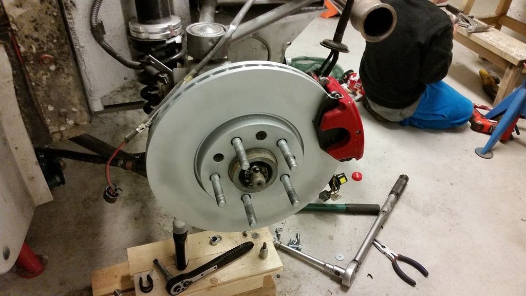
I had some uneven brake pattern on the brake disc, I saved the 2 best but these sat in the front when I bought the car
So they have been machined.
 [/URL
[/URL
The rears I have already bought so it was time to prepair for the season with some for the fronts.
215/40 17 about 223mm wide, when they are loose, 10.5kg.

I thought about making someleather covers for the ununderstandable headrests that is in the way for my LHD converted VX220
and I found a thread here about removing them,so I thought why not and save some weight in the right place on same time.

As a CADer I am I made this little drawing soI could wirecut some plates
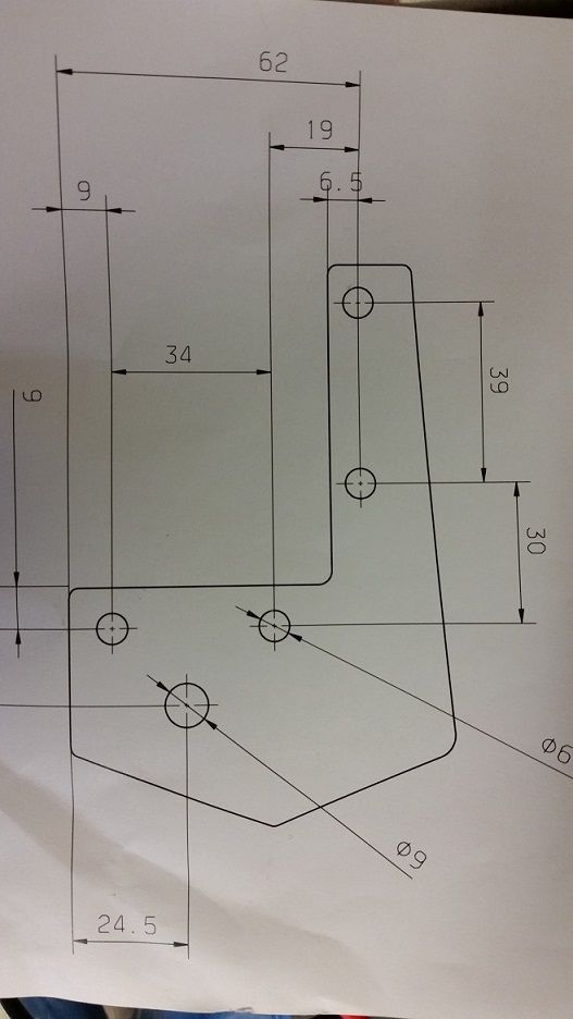
The guy who was going to help me tvisted his leg and couldn´t help me for 2 months.
So a angle grinder was the tool for the job.
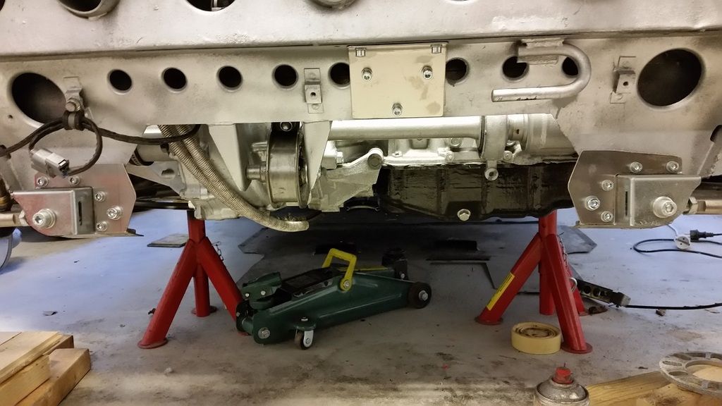
I chose this solution so if I got it rong I wouldn´t mes up the reinforcement plate for the toe link.
And this bracebar plus the reinforcements boxes for the toe link must make this very much more strong than OEM.
But what about a bracebar for front lower A arm connections?!
Almost ready
[URL=http://s954.photobucket.com/user/Axblom/media/bracebar_zpsx6afsk50.jpg.html]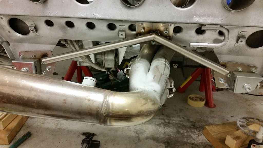
I also did this in the CAD and a friend who have a CNC machine machined it for me.
A small misstake can be seen but it will be covere by carbon vinyl wrap.
It´s a panel for Starter button and my Tunerview 2 mfd and some other buttons.
I´m waiting for a guy to make a analog digitl signal converter for my OEM temp gauge
hope it will come within some weeks, because I´m soon going to start mount everything together.
#498

Posted 19 April 2015 - 05:28 PM
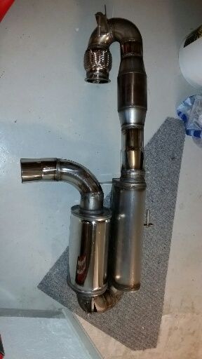
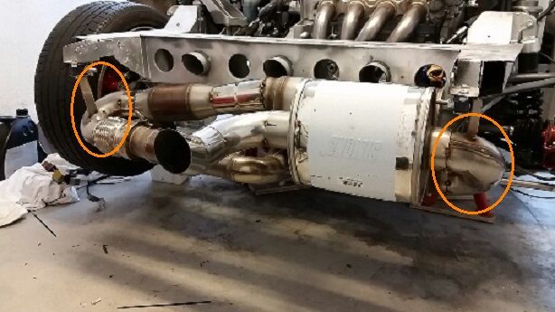
Something I thought about after I saw a picture of a VX220 or Elise somewhere on the net.
Could it be good to put some exhaust wrap on the ends of my exhaust system? (see orange markings)
What do you think? Is the space to tires good enough as it is, about equal on both sides.
Or will exhaust wrap give me some extra margin?
Br, Per
Edited by Aerodynamic, 19 April 2015 - 05:31 PM.
#499

Posted 19 April 2015 - 06:36 PM
I would use exhaust wrap or better still ceramic coating, it will likely melt your arch liners. Well at least your left side one.
http://www.vx220.org...lant/?p=1640091
Edited by Crabash, 19 April 2015 - 06:41 PM.
#500

Posted 26 April 2015 - 07:12 AM
Crabash, on 19 Apr 2015 - 6:36 PM, said:
I would use exhaust wrap or better still ceramic coating, it will likely melt your arch liners. Well at least your left side one.
Thank you Crabash, I will see if I find exhaust wrap or buy some new.
Is there any DIY Ceramic coating?
2 user(s) are reading this topic
0 members, 2 guests, 0 anonymous users


