Jump to content


Photo

Fan Switch Wiring...

wiring

  • Please log in to reply
5 replies to this topic

#1 Dunk

Dunk

    Need to get Out More

  • PipPipPipPip
  • 1,224 posts
  • Gender:Male
  • Location:Edinburgh
  • Interests:WLTM reliable, quiet, tidy one for LTR.

Posted 03 February 2013 - 11:08 PM

Hi all

To put you in the picture, I know somewhere between "very little" and fcuk all about automotive electrics.

When I bought the Batmobile, the cooling fan switch fitted by the previous owner didn't do anything. Not a problem for me as I don't commute in the beast and haven't had any need for it. Having taken the dash plates off yesterday however, I saw that the problem has just been that one of the spade connectors had not been attached properly/come loose.

As I took off the dash plate, the connector made contact with one of the terminals and the fan came on. Great, thinks I; that's an easy fix.

Only problem is, in my haste to get all the ally parts off, I disconnected the remaining wires without taking any notice of where they were originally attached to.

I'm now left with 4 wires sprouting out of the dash and a forrest of 8 terminals to attach to... D'oh!

Posted Image

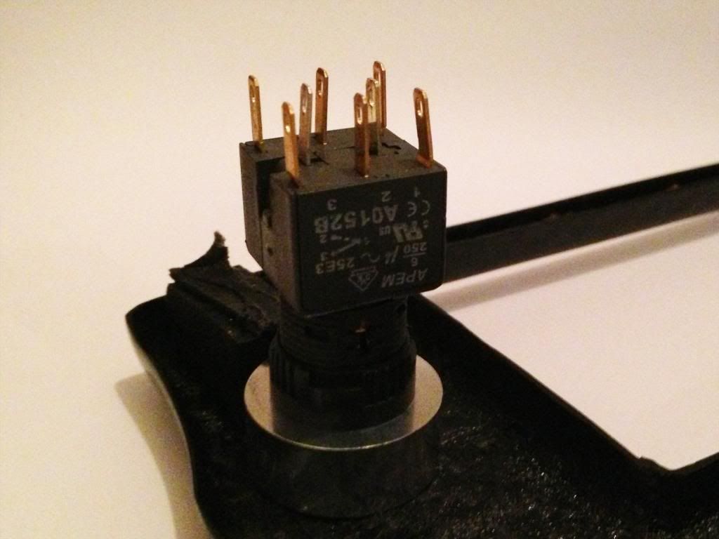
I've got a multimeter and some patience but nothing in the way of practical knowledge. Can anyone help me with an idiot's guide to how I work out what goes where please?

Thanks


Dunk

#2 VXT_NI

VXT_NI

    Member

  • Pip
  • 43 posts
  • Gender:Male
  • Location:Bangor, Northern Ireland

Posted 04 February 2013 - 01:52 AM

Ok, just did a quick Google search and the datasheet for this switch (APEM - A0152B) can be downloaded from Farnell. Google "A0152B"; it's the first search result for me. I'm guessing this switch is illuminated? If so, two of your wires are to illuminate the bulb. I think the two center pins on the switch are for this. (one wire will be a ground and the other will be 12v when either the ignition or lights are turned on) Now for the other two wires. I think they need to be connected to any of the normally open contacts available on this switch. (it is double pole) Looking at the datasheet; it is pins marked as "1" and "2". I can see the same markings from your picture. I hope this helps :)

#3 Dunk

Dunk

    Need to get Out More

  • PipPipPipPip
  • 1,224 posts
  • Gender:Male
  • Location:Edinburgh
  • Interests:WLTM reliable, quiet, tidy one for LTR.

Posted 04 February 2013 - 07:22 AM

Thanks! It's never been illuminated but I guess that's possibly been a loose connection issue too. I'll have s stab at that too :D

#4 -Dab-of-Oppo-

-Dab-of-Oppo-

    Cuntpuffin

  • PipPipPipPipPipPip
  • 3,646 posts
  • Gender:Male
  • Location:Nr. Fordingbridge, Hampshire

Posted 04 February 2013 - 06:16 PM

I have replaced all my switches with ones that look the same as these. I think VXT_NI is correct in all that he says. Since you have 4 wires I am pretty sure two must be for illumination. Can you trace where the wires are going to? I fitted my fan switch by grounding a wire coming from the relay in the front of the car but alot of people choose to do it from a wire running along the middle of the car under the center console. The two pins in the middle are the LED wires you need to have an ignition swithced live going to the positive leg and then bridge the negative accross to leg 4 or 5 then have 4 or 5 grounded to the car. Legs 1 2 3 are seperate to legs 4 5 6 and 3 and 6 will be normally closed. (not needed in your instance)

Edited by -Dab-of-Oppo-, 04 February 2013 - 06:18 PM.


#5 Dunk

Dunk

    Need to get Out More

  • PipPipPipPip
  • 1,224 posts
  • Gender:Male
  • Location:Edinburgh
  • Interests:WLTM reliable, quiet, tidy one for LTR.

Posted 04 February 2013 - 08:03 PM

Thanks Graham. Helpful as always thumbsup :D

#6 Dunk

Dunk

    Need to get Out More

  • PipPipPipPip
  • 1,224 posts
  • Gender:Male
  • Location:Edinburgh
  • Interests:WLTM reliable, quiet, tidy one for LTR.

Posted 30 March 2013 - 08:57 AM

Hey. I finally got the dash plates Dremelled and secured, along with the wiring for this fan override switch yesterday. Used pins 1 & 2 and the two centre pins as advised and it works a treat now! The wires to the centre pins had me foxed for a little while as they are only powered when the headlights are on. Makes sense but the starter button "Start" is permanently illuminated when the ignition is one. Thanks again for your help. thumbsup Imnotworthy


Also tagged with one or more of these keywords: wiring

1 user(s) are reading this topic

0 members, 1 guests, 0 anonymous users