Project 'cash In The Attic' - Sc Conversion
#181

Posted 04 July 2014 - 08:08 AM
#182

Posted 04 July 2014 - 01:18 PM
Chacha - thanks for the offer. I need the plastic bit that sits behind the clam rather than the silver bit in front (sorry about the poor explanation). Would be great if you had a spare :-)
#183

Posted 06 July 2014 - 05:10 PM
http://www.polevolt...._to_length.html
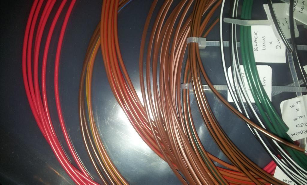
Get a meter of half the colours, from memory the injector wires are something like yellow/brown yellow/black, yellow/red and yellow/blue, so get black, brown, yellow, blue, add a few more meters of black as you'll use that for a few other things, and 3 meters of 1.0mm green for the MAP and fuel vent. will also need 2 m of red 1.0 mm and black for the CC pump.
Brilliant - thanks! Just about to make an order
#184

Posted 08 July 2014 - 10:41 AM
I was talking to Stuwy about this in the pub on Friday. When I took my rear clam off the plastic that the bolts go into was damaged but still usable. I did some searching on here and iirc it's quite a large section that has that on it and was reasonably expensive.
Found the bit that I believe is correct.
part # 9198028
http://www.autovaux....fillerneck.aspx
#186

Posted 08 July 2014 - 08:05 PM
Time for a bit of a progress update (as it's pouring with rain which is stopping me getting on... grrrr).
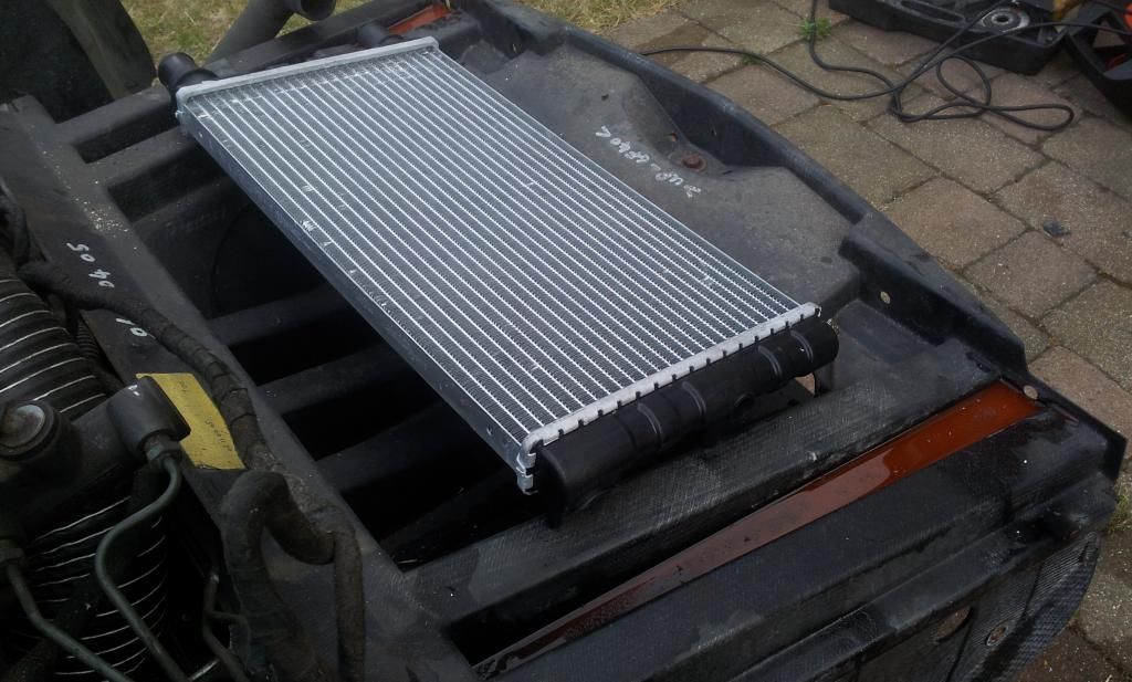
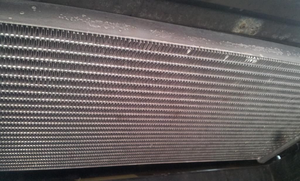
First up, the charge cooler rad. I was planning to go for an alternative approach here and use a fiat seicento/cinquicento rad. This set up has been successfully installed by a chap with a turbo Elise.
Measuring up:-
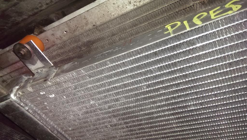
While the rad will physically fit it really needs new ends fabricating to work properly and some brackets welding on to the side - this is the approach the Lotus guy used (not my car...):
I was hoping to try and make up some brackets and bolt it up but doing it that way would mean the 1/2" outlets are going to foul on the main rad - it needs the end caps replacing like above. So... - a call to the Batman has been made and a pro-alloy main rad and CC rad are due to arrive in the next couple of weeks (Thanks Joe!!!).
The original budget has long gone out the window so this takes me into massive overspend. It may have been cheaper to go for a Joe/Lee conversion and save the hassle but I'm enjoying the process (or so I keep telling myself).
Next up... wiring..
I checked out the colours in the loom and for future reference they are:
Injectors:
- Brown/Pink : Brown/Red
- Brown/Pink : Brown/Blue
- Brown/Pink : Brown/Green
- Brown/Pink : Brown/Yellow
MAF:
- Green
- Black/White
- Black/Brown
Charcoal thingy (If I have the correct wire)
- Brown/Pink
- Brown/Red
PoleVolt has a really good selection of colours in their 1.0mm cable so I've ordered all the right colours from them. Just needs fitting (when the rain stops):
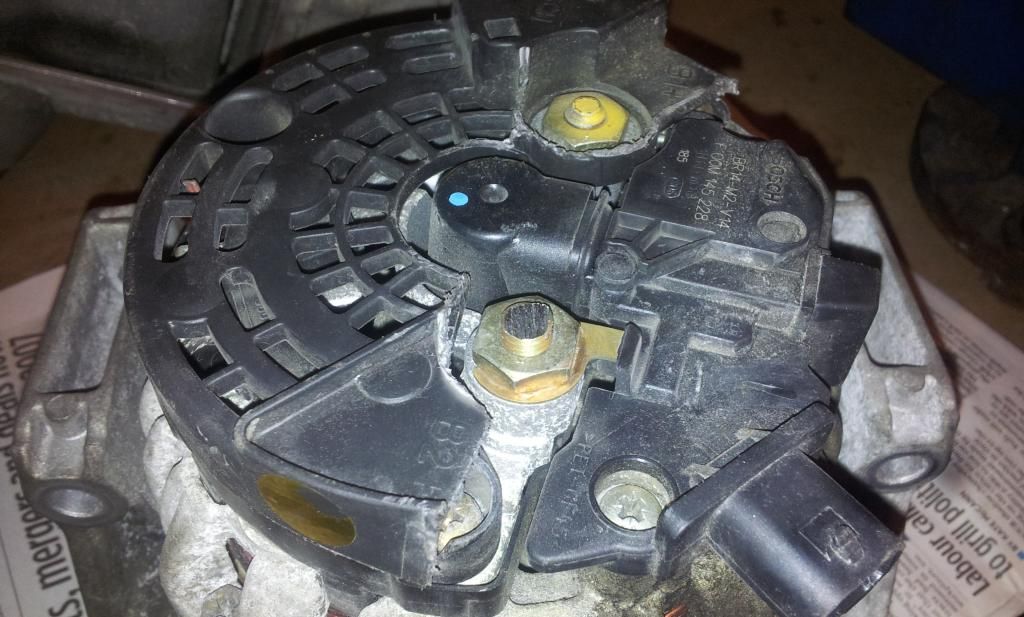
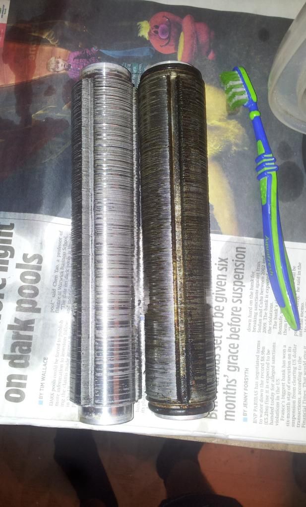
While it's raining (did I mention the rain?), I've modified the alternator and cleaned the Laminovas (before and after)...
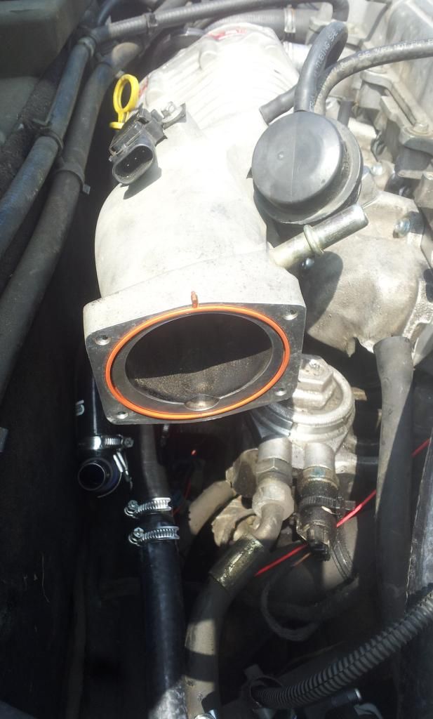
Throttle body, inlet manifold, alternator are all off the car so I can start wiring and fitting new bits (when it stops raining)..
Edited by Captain Vimes, 08 July 2014 - 08:07 PM.
#187

Posted 09 July 2014 - 11:19 PM
So - just thinking through the rest of the conversion.
I'm completely confused on what to do with the PCV and oil breather set up.... as the inlet is off at the moment, I could modify the inlet gasket but not sure whether this is the best approach.
I've also got a catch tank and small filter so can add them to the system if needed.
Any recommendations?
Also, can someone confirm the hose size I need to use if adding hose to the oil breather 'system'? Is it a 16mm ID?
#188

Posted 10 July 2014 - 07:25 AM
It's 13mm.
Even the GM build book modifies the original gasket, the other option is cut your own or source a phenolic one from ZZP with the correct cutout.
#189

Posted 10 July 2014 - 09:04 AM
Thans Fez.
The confusion is that other threads mention that Courtenay don't modify the gasket. I thought there might be a good reason but happy to go with the GM approach.
For the PCV and cam breather. I was thinking of sending then both to a catch tank with 3 outlets. The 3rd hose would have a filter attached and located in the wheel arch.
Does that make sense?
#190

Posted 10 July 2014 - 09:14 AM
No it doesn't.
The PCV and cam breather are one and the same. PCV (positive crankcase ventilation) describes the entire system, consisting of:
- Cam breather (fresh air, filtered by the main air filter is drawn in from here when there is inlet manifold vacuum)
- PCV valve, open when the pressure in the inlet manifold is lower than the pressure in the crankcase, allowed dirty air (carrying oil and combustion vapours) out into the inlet manifold, where it is burnt during combustion
when the PCV valve closes due to boost pressure in the manifold, the crankcase pressure is forced out of the cam breather, this is where the throttle body and laminovas can become contaminated.
Courtney don't modify the gasket because their map doesn't work with it. Those cars don't run a working PCV valve, instead all vapours are vented through the cam breather. This smells, and it causes oil 'bumping' where more oil is blown out due to the reversing air flow (air is both exiting and entering the same pipe).
To address your questions, the PCV valve is in the inlet manifold and mates directly to the cylinder head PCV channel, there's no room to send it to a catch tank, nor is there need to as it's after the laminovas.
I would suggest you place a catch tank on the cam breather, and either connect to the inlet or remove the risk of contamination by putting a small separate filter on the hose.
#191

Posted 10 July 2014 - 10:14 AM
Edited by CHILL Gone DUTCH, 10 July 2014 - 10:15 AM.
#192

Posted 10 July 2014 - 10:25 AM
I'm going to keep it oem but have a inline catch tank with separators
Linky?
#193

Posted 10 July 2014 - 11:21 AM
No it doesn't.
The PCV and cam breather are one and the same. PCV (positive crankcase ventilation) describes the entire system, consisting of:
- Cam breather (fresh air, filtered by the main air filter is drawn in from here when there is inlet manifold vacuum)
- PCV valve, open when the pressure in the inlet manifold is lower than the pressure in the crankcase, allowed dirty air (carrying oil and combustion vapours) out into the inlet manifold, where it is burnt during combustion
when the PCV valve closes due to boost pressure in the manifold, the crankcase pressure is forced out of the cam breather, this is where the throttle body and laminovas can become contaminated.
Courtney don't modify the gasket because their map doesn't work with it. Those cars don't run a working PCV valve, instead all vapours are vented through the cam breather. This smells, and it causes oil 'bumping' where more oil is blown out due to the reversing air flow (air is both exiting and entering the same pipe).
To address your questions, the PCV valve is in the inlet manifold and mates directly to the cylinder head PCV channel, there's no room to send it to a catch tank, nor is there need to as it's after the laminovas.
I would suggest you place a catch tank on the cam breather, and either connect to the inlet or remove the risk of contamination by putting a small separate filter on the hose.
I presume you could fit an inline non return valve in the breather where it goes into the inlet, to remove the chance of contamination?
#194

Posted 10 July 2014 - 11:27 AM
Nope, otherwise you effectively block the breather system when the PCV valve closes under boost.
#195

Posted 10 July 2014 - 11:53 AM
might be an idea to replace PCV valve in the SC inlet manifold, because it might need replacing due to old age.
Edited by vocky, 10 July 2014 - 12:16 PM.
#196

Posted 10 July 2014 - 12:13 PM
Thanks all - especially Fez for your great description. I finally get it (possibly)!
So I'll modify the gasket to allow the PCV to work - this is a no brainer.
Cam breather has a few options:-
- connect to inlet directly (Chill has seen blackening in the inlet wit hthis approach)
- connect to small air filter and place it in the wheel arch (Chill has seen a very dirty rear end with this approach - ooeerr!)
- connect to catch tank, then to inlet (Chill's next step) - keep catch tank sealed
- connect to catch tank, then to filterred vent (possibly not much benefit over option2, except to avoid the messy rear end)
- connect to catch tank and feed catch tank to BOTH inlet and filterred vent.
There may be more permutations.
Option 5 looks promising to me (obviously with breather plumbed to the inlet pre-charger). Any thoughts on this?
#197

Posted 10 July 2014 - 01:20 PM
FYI: If you feed back to inlet it must be pre throttle body.
One other thing I have considered is the effect on octane on the inlet charge when mixing oil vapours into the inlet. Apparently it does lower it and supposedly have chance of causing knock/retard/det.
#198

Posted 11 July 2014 - 02:21 PM
Cuts to the manifold gasket to enable the PCV are described here: https://z22se.co.uk/...ck_to_250hp.pdf
#199

Posted 13 July 2014 - 08:18 AM
:Cuts to the manifold gasket to enable the PCV are described here: https://z22se.co.uk/...ck_to_250hp.pdf
#200

Posted 13 July 2014 - 09:23 AM
I had most of yesterday on the car and got quite a bit done.
The biggest headache was trying to solder the loom. After trying to solder for over an hour and only having done 2 wires I decided my soldering iron was in need of replacement and some fresh (fluxed) solder would help. A quick run down to maplin and the difference was night and day. Started again and had nice flowing solder that actually stuck to the wires ![]()
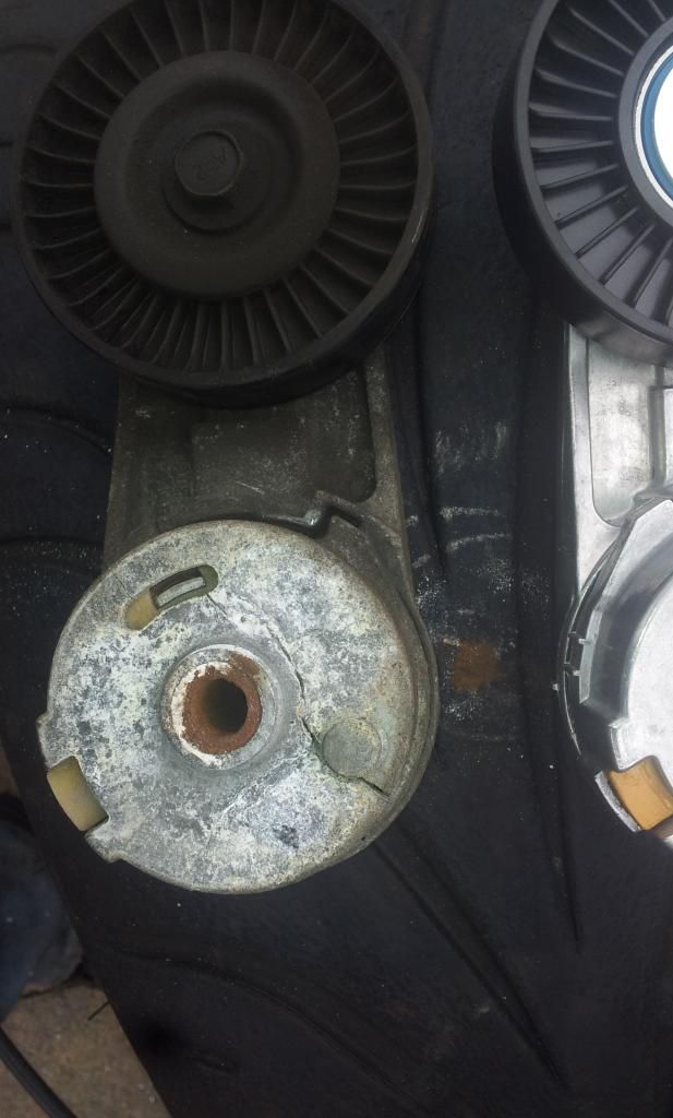
Step 1:- Replace broken tensioner with new shiny one:-
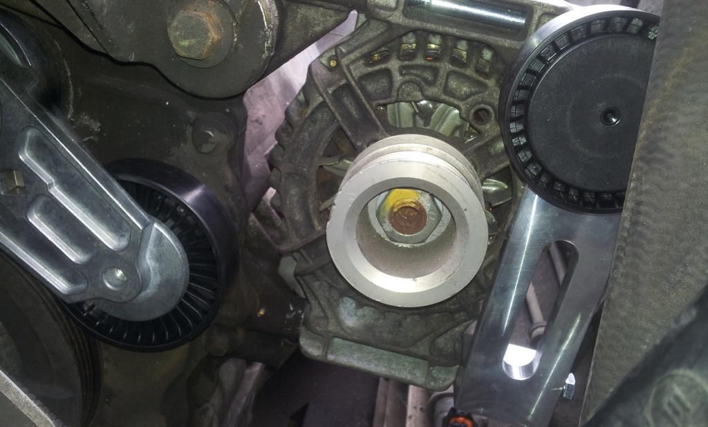
Step 2:- Bolt up modified alternator, new tensioner and pulley bracket - nice to see shiny bits going back on the engine ![]()
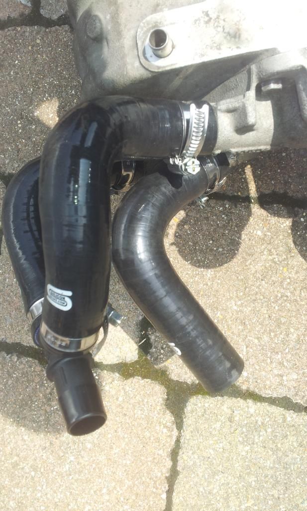
Step 3:- Fit manifold bracket and get the dual pass manifold ready to fit into the car:-
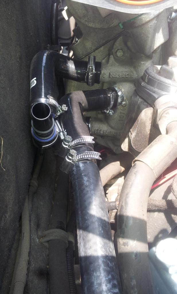
Step4:- Fit the manifold, and check the pipes all fit:
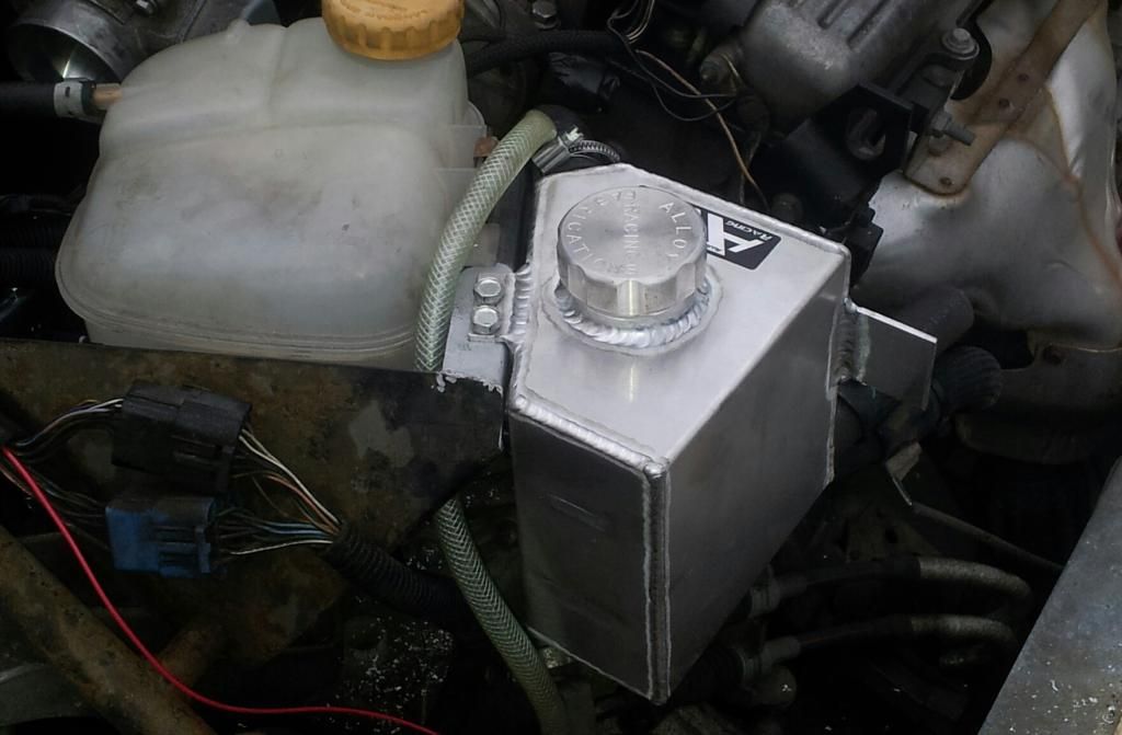
Step 5:- Fit the Alloy header tank:-
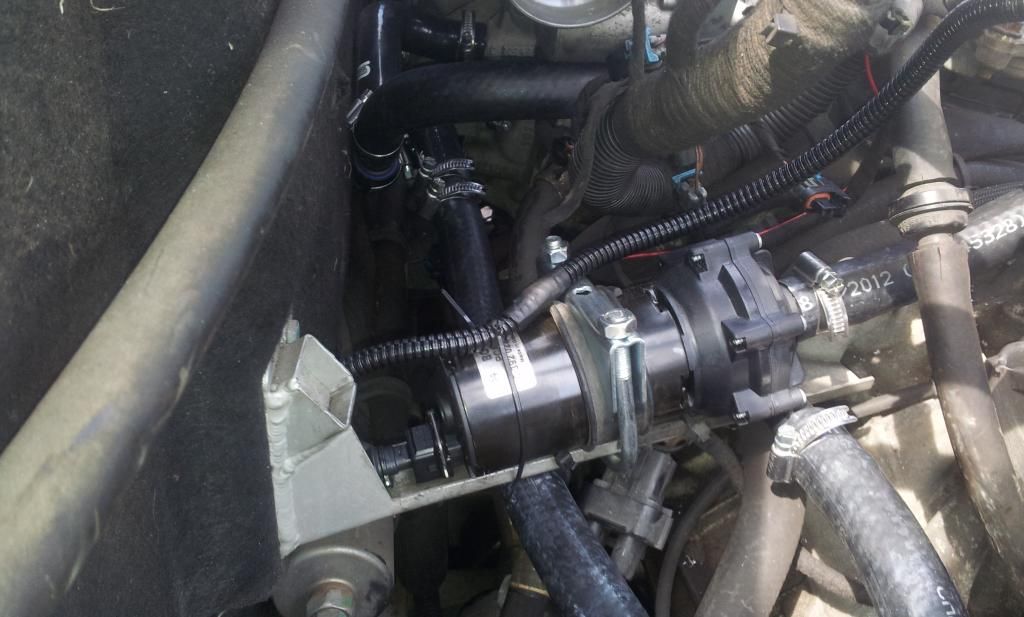
Step6:- Fit Charge cooler pump and plumb all the hoses in:-
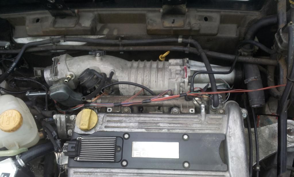
Step7:- Fit the Supercharger. I discovered that I already had a TB gasket in the box from America - which was a nice result:-
Step8:- Fit the blue injectors to the fuel rail, Rewire the MAP sensor, charcoal thingy, injectors and fit clips (I've got some nice black tubing and tape to cover the wires, I'm not leaving it like this):-
Step9:- Retire indoors after the thunder started and drink a cold beer (no picture...)
Not far from getting it started now but still have some key things to do - like bolt in the bottom of the manifold, fuel pipes, belt, relay for CC pump etc... Should be starting it up next week ![]()
3 user(s) are reading this topic
0 members, 3 guests, 0 anonymous users


