Measuring Front Bumpsteer, Wtf
#41

Posted 22 January 2014 - 11:59 AM
#42

Posted 22 January 2014 - 12:19 PM
Edited by 2-20, 22 January 2014 - 12:26 PM.
#43

Posted 22 January 2014 - 01:34 PM
#44

Posted 22 January 2014 - 01:41 PM
that's not adjustable, it's just an ali replacement steering arm.The sector 111 kit is cheaper and use the standard rod ends http://www.sector111...SCN1145 (3).JPG
#45

Posted 22 January 2014 - 02:04 PM
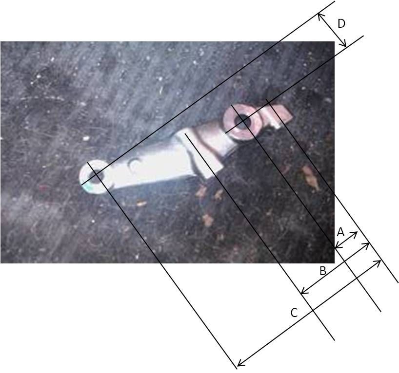
Looking for these dimensions:

plus hole diameters
#46

Posted 22 January 2014 - 11:41 PM
Ah, now I see it, indicated "from" price is for the rod ends only. I thought it was for the arms only. Silly me, how can I even imagine that some high precision CNCed pieces of aircraft grade aluminium can cost less than 100 quid. I think I just make one myself for measurement purposes only. Doesn't have to be fancy. Like to see what it actually does. And DIY means I can change it around a bit too when I like. Does someone perhaps have one of these left side arms lying around and make a simple drawing with dimensions. Or mail it to me (will gladly pay for mailing). Otherwise I have to remove it from my car just to get the right dimensions and put it back on again as I do use the car. I'd rather prepare everything before spending a day measuring.
Alex,
I have some new OEM steering arms lying around (for easy measurement) and in the shed I must have an old bend one that may be well suitable forsome heavy modding. Will take a look
#47

Posted 23 January 2014 - 08:24 AM
Thanks, but managed to measure the whole thing yesterday. Only thing I couldn't get undone was the ball joint. And I couldn't find my ^&%$££ calipers. Now just have to find the time to make an arm. And a ball joint removal tool, as I don't think it's that good of an idea to hammer the thing out. And out it has to come.
Offset to the inside is about 30mm. When you move it more to the outside, you lose Ackermann (not Mr. Ackermann himself, his differential steering angles). So perhaps you make bumpsteer better, but you also make Ackermann worse. Correct?
#48

Posted 23 January 2014 - 02:49 PM
define better?
as I keep saying, you need bumpsteer, without it, the steering feel is somewhat odd and it's responsiveness compromised.
#49

Posted 23 January 2014 - 08:00 PM
Thanks, but managed to measure the whole thing yesterday. Only thing I couldn't get undone was the ball joint. And I couldn't find my ^&%$££ calipers. Now just have to find the time to make an arm. And a ball joint removal tool, as I don't think it's that good of an idea to hammer the thing out. And out it has to come.
Offset to the inside is about 30mm. When you move it more to the outside, you lose Ackermann (not Mr. Ackermann himself, his differential steering angles). So perhaps you make bumpsteer better, but you also make Ackermann worse. Correct?
Alex, I have an old but straight left side steering arm that you can use/modify to your liking. Saves you with messing the upright and baljoint mountings, so you can just alter the steering arm point.
Can chuck it in the mail if you pm me an address. ;-)
Edited by Exmantaa, 23 January 2014 - 08:00 PM.
#50

Posted 24 January 2014 - 07:52 AM
define better?
as I keep saying, you need bumpsteer, without it, the steering feel is somewhat odd and it's responsiveness compromised.
I don't want to remove bumpsteer, but from the bumpsteer measurement it looks like bumpsteer is compromised in the wrong direction. My aim is to get it back to where it's meant to be originally. Or at least closer to that. Is that better? I don't know. I'm sure it will differ on track vs on road. TBH, for me it just feels wrong that the back side is so well controlled, even when lowered, while the front isn't. That's the main reason I want to get it back 'in line'.
In the mean time I learn something about suspension geometry. Hence all the questions. All too easy to optimize bump steer only to find out that you compromised something else. Like Ackerman in this case. Having Ackerman is a good thing and I certainly don't want to throw it away trying to remove some bumpsteer. Having said that, I don't know what the 'optimum' is in a compromise between Ackerman and bumpsteer. So I try to avoid that compromise if possible.
It's also clear that going from 140mm to 115mm ride height, you get into an area that you're not supposed to go into. Trying to solve that by changing a pick up point improves it a bit, but you'll never get it right. E.g. change in camber around 140 and 115mm. Right as in: full Ackerman, camber change minimal, fixed low roll center, some bumpsteer in the right directions, but not too much, etc.
#51

Posted 24 January 2014 - 08:07 AM
Thanks, but managed to measure the whole thing yesterday. Only thing I couldn't get undone was the ball joint. And I couldn't find my ^&%$££ calipers. Now just have to find the time to make an arm. And a ball joint removal tool, as I don't think it's that good of an idea to hammer the thing out. And out it has to come.
Offset to the inside is about 30mm. When you move it more to the outside, you lose Ackermann (not Mr. Ackermann himself, his differential steering angles). So perhaps you make bumpsteer better, but you also make Ackermann worse. Correct?
Alex, I have an old but straight left side steering arm that you can use/modify to your liking. Saves you with messing the upright and baljoint mountings, so you can just alter the steering arm point.
Can chuck it in the mail if you pm me an address. ;-)
Thanks a lot for the offer, but it looks like I have to move the pick up point down. First have to do some calculations to see if that makes sense. I don't want to just chuck something on while having no clue what it does.
In the mean time, perhaps you can get that group buy for uprights going ![]() (at 115mm the standard upright turns into an upwrong)
(at 115mm the standard upright turns into an upwrong)
#52

Posted 24 January 2014 - 08:15 AM
Lotus has done some specific steering arms for the 2-11.(with a lower mounting point)
They perhaps realised that the forged ones were too compromised.
#53

Posted 24 January 2014 - 09:37 AM
Number 4 here:

Part: C127C0003F and C127C0004F
Pricey at £316.03 though..
The diagram doesn't show it really, but the 2-11 upper front wishbone also has an angled balloint socket/eye to keep the balljoint angles more 'straight' at the ride height they run.
Perhaps also a bit of a bodge, but hey ![]()
Bye, Arno.
#54

Posted 24 January 2014 - 11:10 AM
Thanks for that. From that drawing I understand why the guy who designed the Sector111 V2 arms mentions in some thread he had to laugh about how similar they look to the Lotus 211 arms, even though he started from a blank piece of paper. Also looks like these: http://www.elisepart...-steering-arms/ EP arms. Both drop the linkage point while keeping the offset for Ackerman. Also seems that both move the offset of the balljoint to allow for more camber.
#55

Posted 24 January 2014 - 11:45 AM
how symmetrical are the forged arms , can you swap L and R over , to get a lower position for the trackrod

#56

Posted 24 January 2014 - 12:21 PM
how symmetrical are the forged arms , can you swap L and R over , to get a lower position for the trackrod
They are symetrical before being machined.
After , they are reamed to a conical shape for the ball joints and they cannot be swaped
#57

Posted 24 January 2014 - 12:25 PM
Thanks for that. From that drawing I understand why the guy who designed the Sector111 V2 arms mentions in some thread he had to laugh about how similar they look to the Lotus 211 arms, even though he started from a blank piece of paper. Also looks like these: http://www.elisepart...-steering-arms/ EP arms. Both drop the linkage point while keeping the offset for Ackerman. Also seems that both move the offset of the balljoint to allow for more camber.
Geary told me that the effect on bumpsteer is very minimal with these as the difference is just a few millimeters.
However, they look similar to the V2arms ( and to the EP adjustable ones but the rod ends installation heigth might also be lower on them)
#58

Posted 24 January 2014 - 05:40 PM
Thanks, but managed to measure the whole thing yesterday. Only thing I couldn't get undone was the ball joint. And I couldn't find my ^&%$££ calipers. Now just have to find the time to make an arm. And a ball joint removal tool, as I don't think it's that good of an idea to hammer the thing out. And out it has to come.
Offset to the inside is about 30mm. When you move it more to the outside, you lose Ackermann (not Mr. Ackermann himself, his differential steering angles). So perhaps you make bumpsteer better, but you also make Ackermann worse. Correct?
Alex, I have an old but straight left side steering arm that you can use/modify to your liking. Saves you with messing the upright and baljoint mountings, so you can just alter the steering arm point.
Can chuck it in the mail if you pm me an address. ;-)
Thanks a lot for the offer, but it looks like I have to move the pick up point down. First have to do some calculations to see if that makes sense. I don't want to just chuck something on while having no clue what it does.
In the mean time, perhaps you can get that group buy for uprights going
(at 115mm the standard upright turns into an upwrong)
yeah, you will have to move the steering pick-up point down, but you can do what you like with that am;
Use it for measurement. Saw it off and/or weld a threaded piece onto it on which you can attach a normal open balljoint. Then move it up or down to see where it brings you.
Ackerman should not be affected (I think) as long as you keep the horizontal position the same.
#59

Posted 27 January 2014 - 11:16 AM
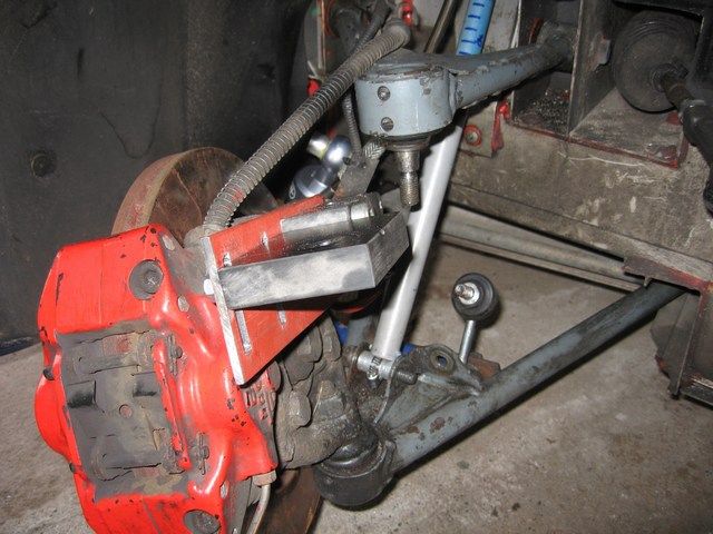
First made this:

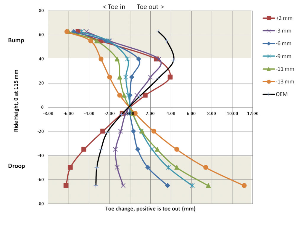
Allows me to vary the height of the pickup point of the steering arm. Results (OEM is the original steering arm, which is already 4 mm lower than the pick up point of the swing arm)

The bumpsteer curve is very sensitive to vertical movements. From some calculations I did, that makes sense. Did some drawings and calculations with the whole thing getting pretty complex with changing radii, origins, phases etc. Small wonder the curves get funny too. Another thing to keep in mind is that 1 mm movement at the steering arm is 4 mm at the rim.
You can get a bumpsteer curve in whatever direction you prefer. 3-4 mm down from OEM looks like a winner. At least for me with th very limited practical experience I have. Lower than that either means no bumpsteer, or going toe in instead of out.
Some comments:
- the areas in grey are where you normally will not go, droop due to shock length and bump due to bumpstop. With my Nitrons, total travel at the wheel is 60mm. With some bumpstop about 70-75mm
- the rather violent move to the left at full bump of the measured curves is probably due to movement in my concocted steering arm and the track rod hitting it and pulling it down. I'm not sure about this, as I only analyzed the data afterwards, so didn't notice anything when measuring. I used a jack to move the upright, wouldn't have noticed a little more force. It just doesn't look right and the OEM curve doesn't show this behaviour, so something must have gone wrong
- I didn't tighten the balljoint nuts as you do with the OEM arm. First reason is the material I used (a kind of plastic which is like a soft aluminium), the second is that I can't make tapered holes, so I did them in 3 steps. result is that there might be a small error in relative height
Edited by techieboy, 27 January 2014 - 11:27 AM.
fixed image embeds
#60

Posted 27 January 2014 - 12:09 PM
Thanks Alexb,
One question: Is your 115 mm ride height with 16'' or 17'' wheels ?
I assume with 16''
Thank you
Edited by 2-20, 27 January 2014 - 12:10 PM.
1 user(s) are reading this topic
0 members, 1 guests, 0 anonymous users


