yep, i wont use a proper pressure bleeder, probably just gravity feed most of the line, spend a while burping the slave manually, then get it all together and bleed it manually.

Project Fracas - 6Sp A20Nft
#741

Posted 12 October 2017 - 08:53 AM
#742

Posted 12 October 2017 - 08:53 AM
Edited by Doctor Ed, 12 October 2017 - 08:53 AM.
#743

Posted 12 October 2017 - 11:39 AM
#744

Posted 12 October 2017 - 07:40 PM
yep, i wont use a proper pressure bleeder, probably just gravity feed most of the line, spend a while burping the slave manually, then get it all together and bleed it manually.
reverse bleed it ![]()
ps: push the slave cylinder inwards as you release the bleed nipple, tighten the nipple when it is fully depressed, repeat until no air comes out
#745

Posted 12 October 2017 - 08:05 PM
#746

Posted 15 October 2017 - 08:55 AM
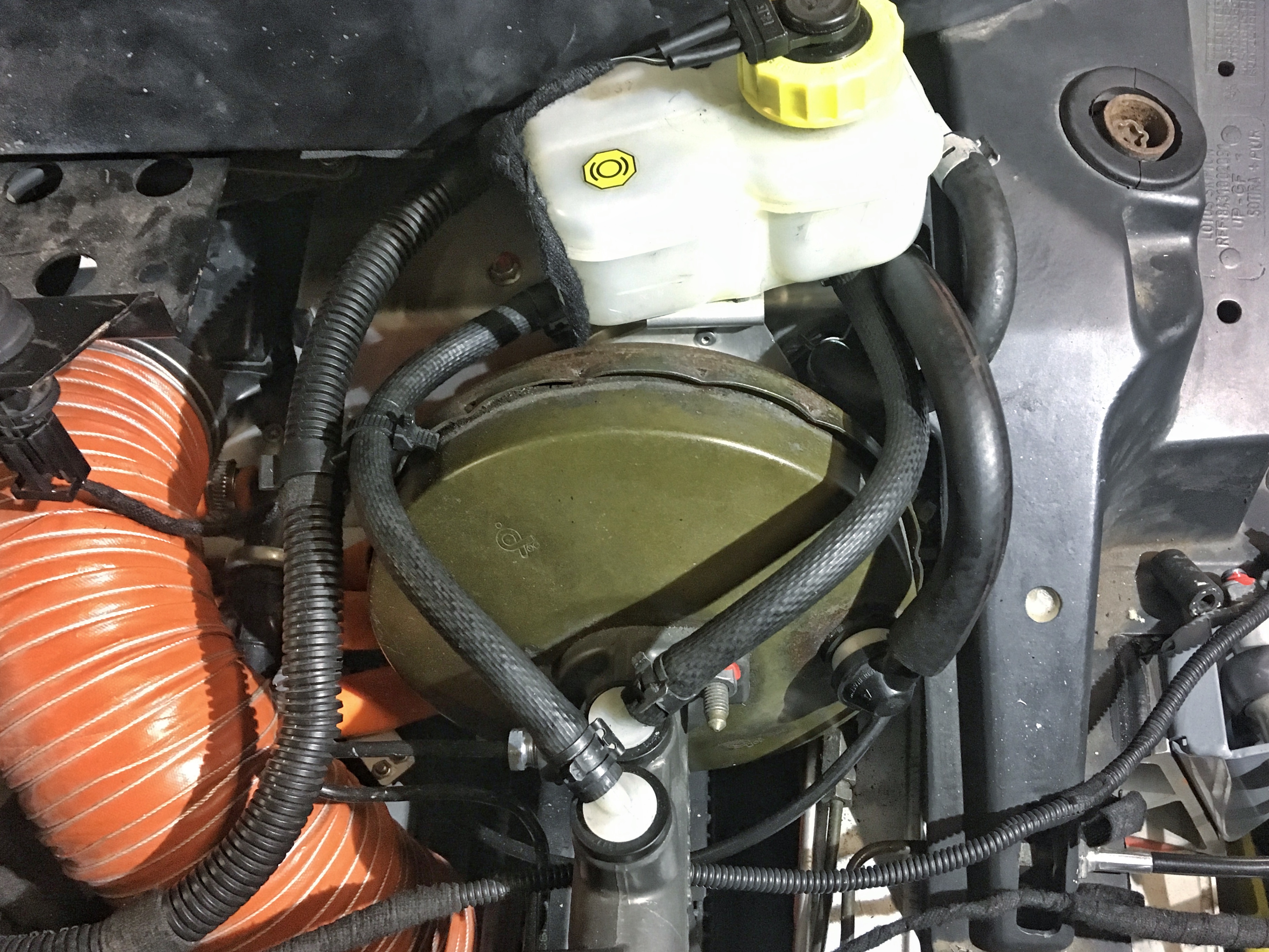
first up, the heartache that is the brake reservoir and fittings finally had an ending. found a guy wrecking a LHD on gumtree, and although cost more than it shoudve (LHD tax) finally got the required bits to put things together. i modified the way some things run in order to neaten it all up a little. also repurposed some unused coolant hose for the clutch reservoir line. its EPDM so should be brake fluid resistant. hope so!
then moved back along the chassis, and got the fuel tank shear panel and the rear control arm mounts /gearbox torque mounts in properly. done
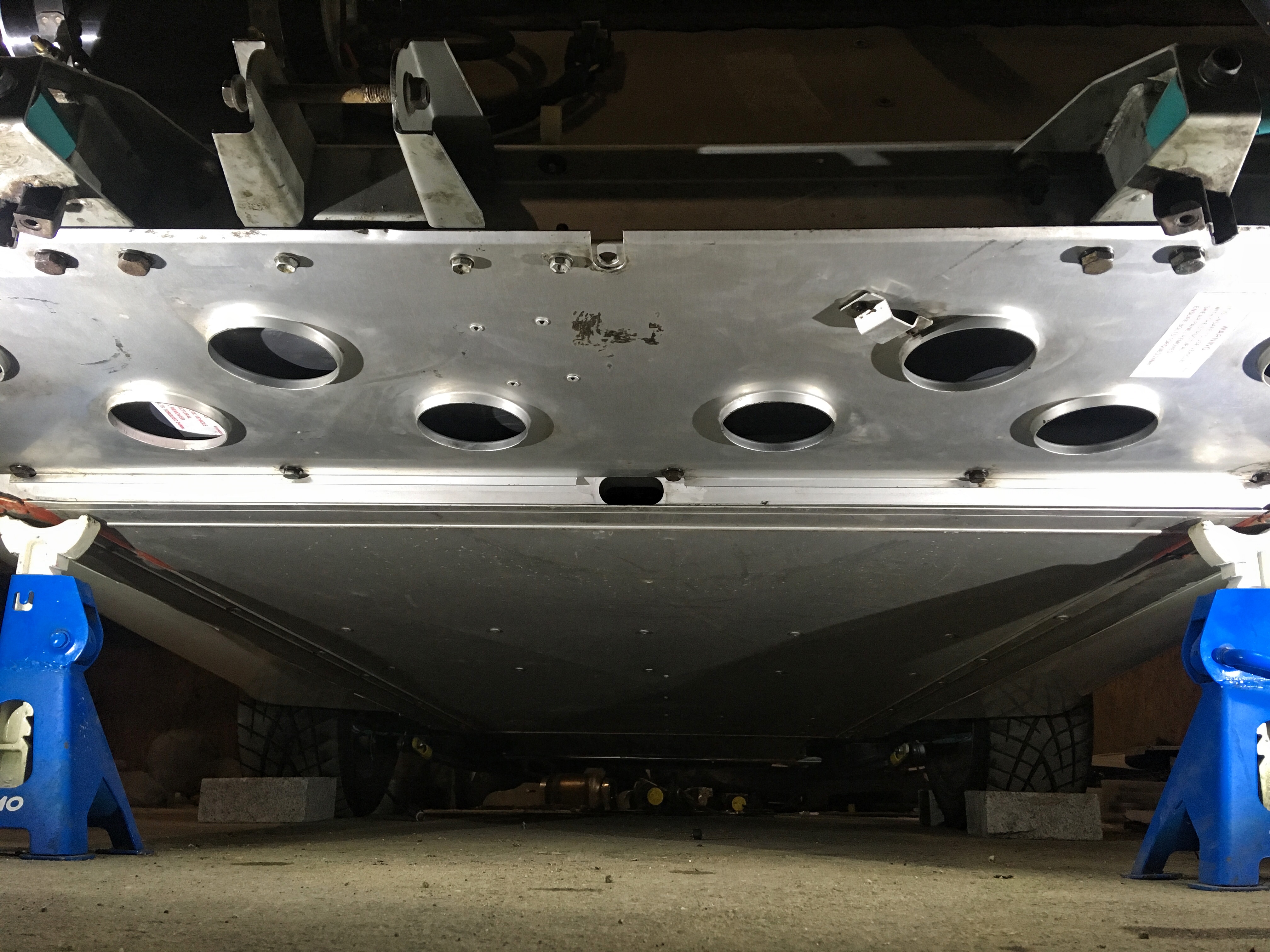
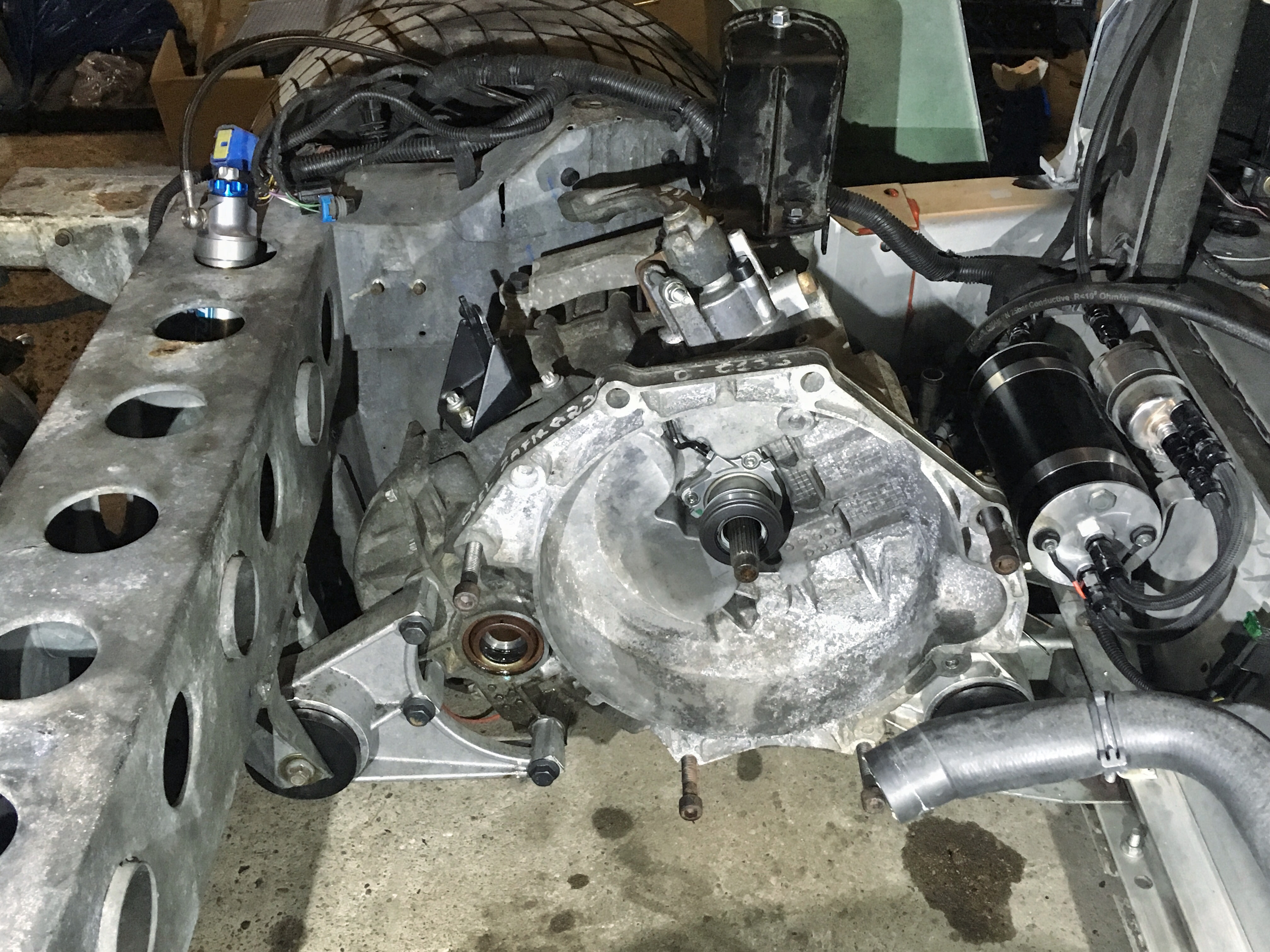
pulled the slave cyl off in mild paranoia that id buggered the backing plate/seal, confirmed everything is where its supposed to be and slides freely, then in a delirious haze of '2:30am i should probably go home now' with the back of the car jacked up to get to the shear panel, i looked at the gearbox and was like... well why not. so dragged the gearbox in under the chassis on the jack. offloaded it, dropped the chassis, and then manually heaved the box into position. slipped the jack back in for fine positioning, slipped the bolts in. voila! gearbox is kindve in. went home in a delirious haze of satisfaction
Edited by Doctor Ed, 15 October 2017 - 09:00 AM.
#747

Posted 15 October 2017 - 10:26 AM
when you fit the engine remove the crank pulley and oil pump, it will then go in very easily ![]()
#748

Posted 15 October 2017 - 10:46 AM
#749

Posted 15 October 2017 - 12:54 PM
you would need to remove one bolt from the water pump access panel - it will be obvious which one
it's a pain to get the clutch past the bellhousing, a crowbar helps, but it can be done
#750

Posted 16 October 2017 - 12:28 PM
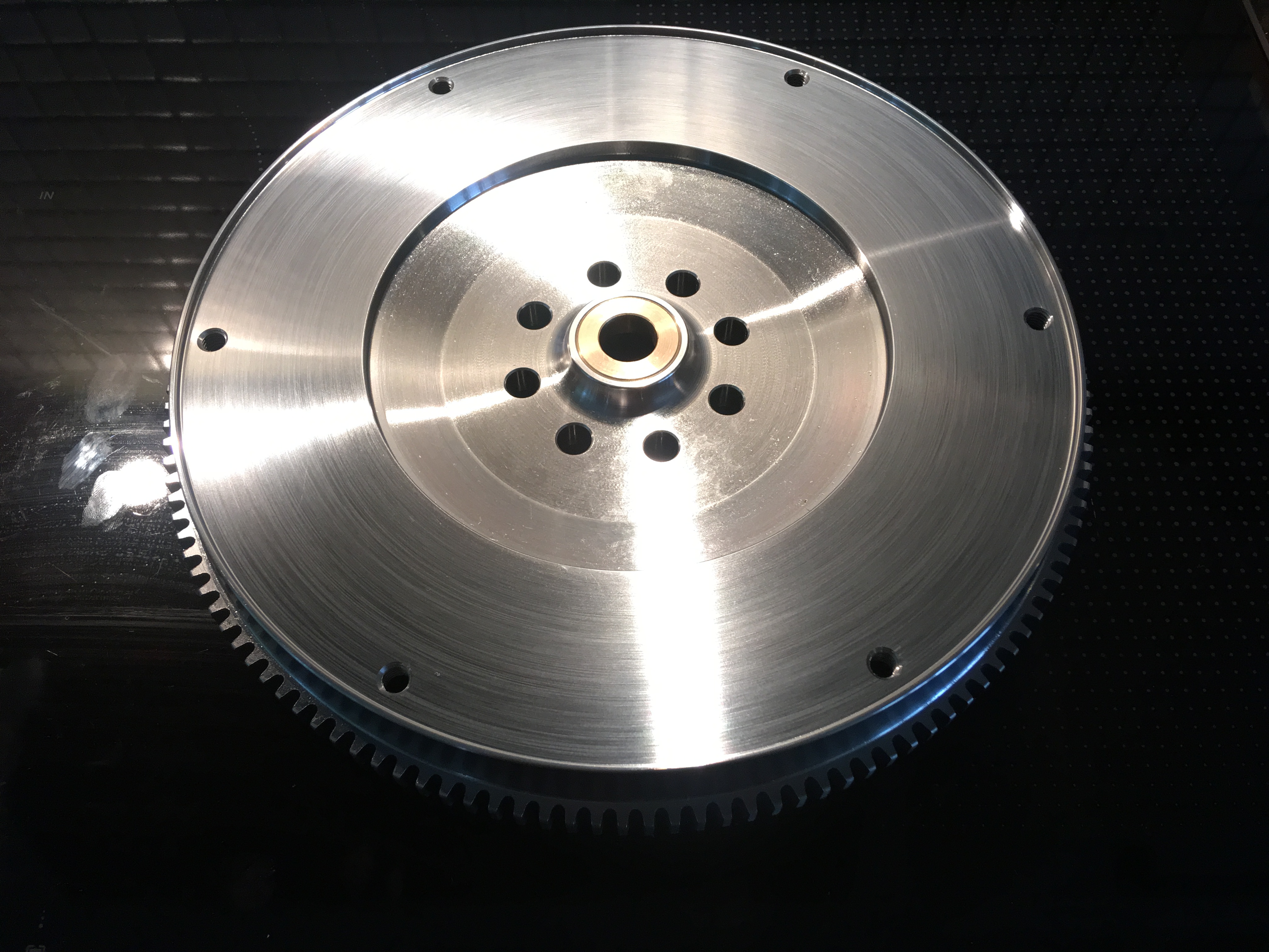
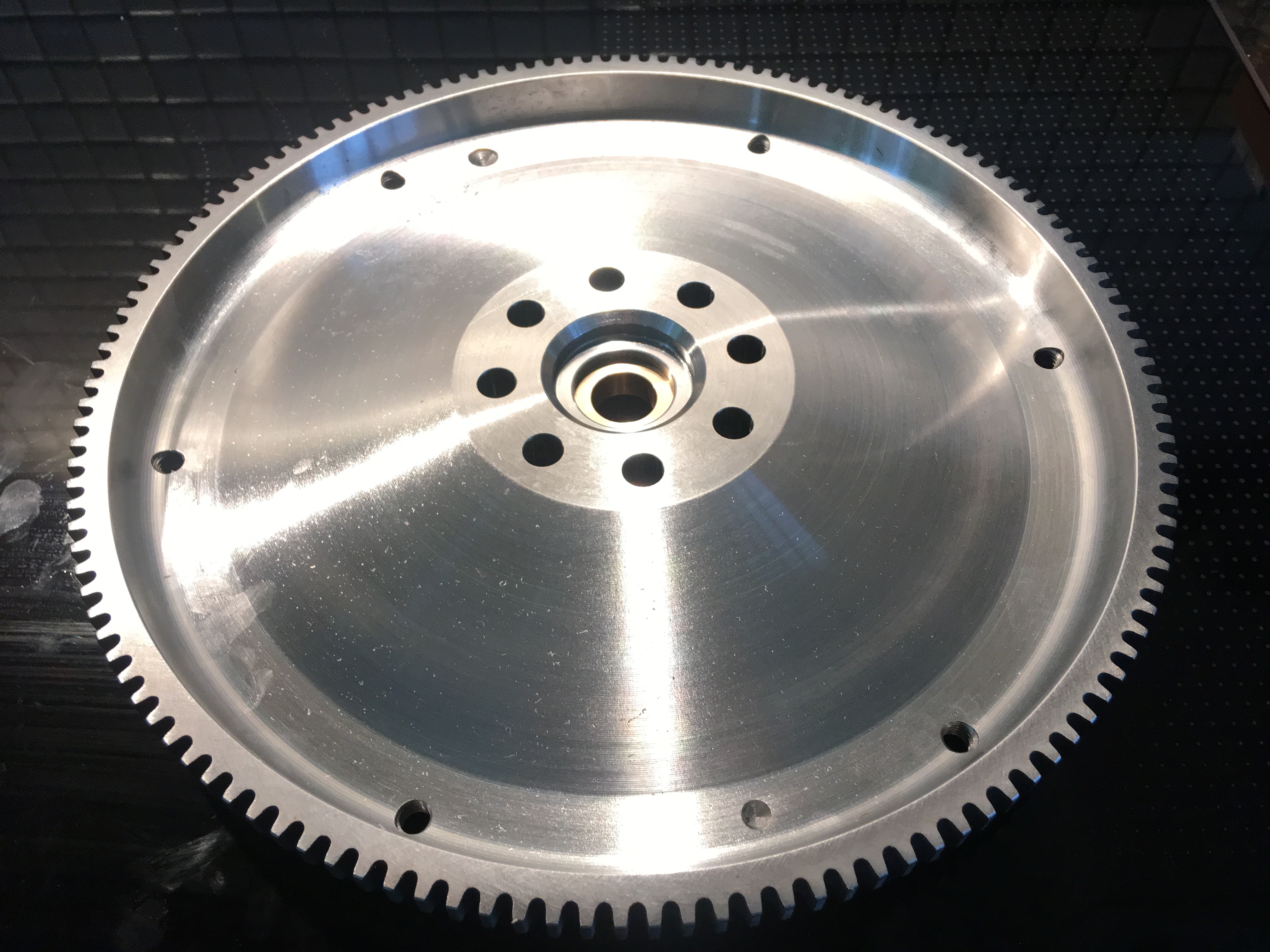
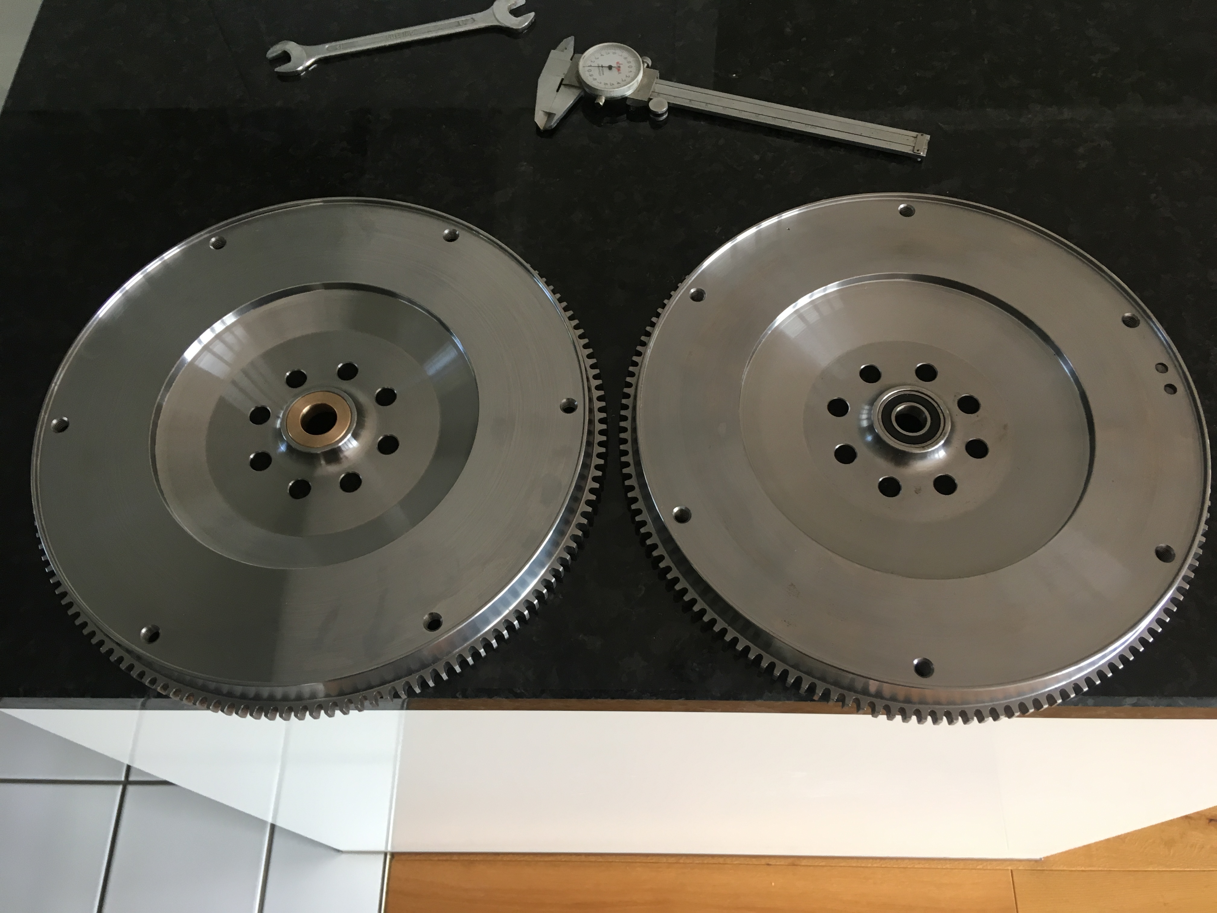
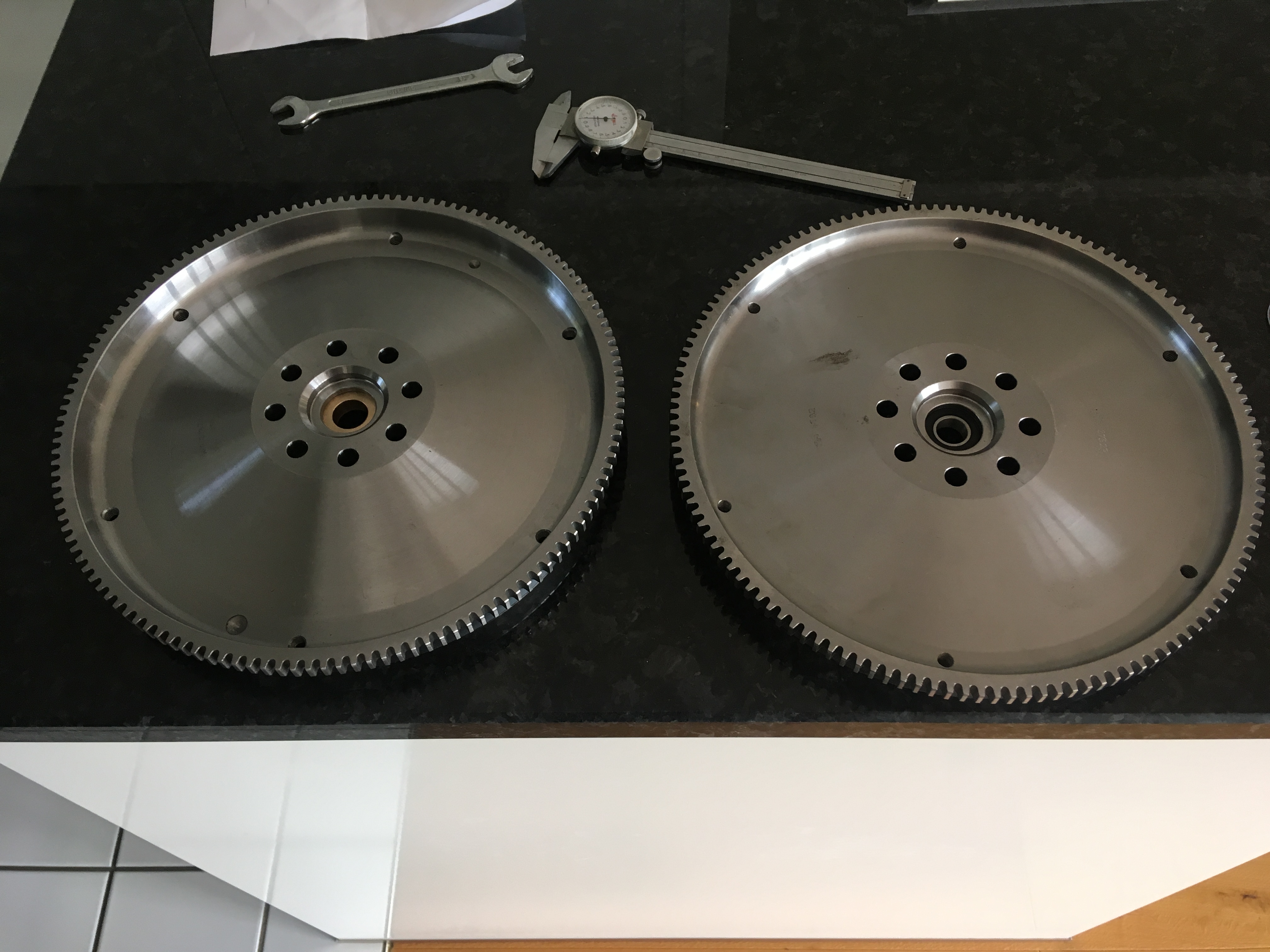
Revised friction surface, revised spigot bush, revised weight...
Comes in at 5.4kg (2kg reduction over v1)
#751

Posted 16 October 2017 - 01:23 PM
2kg lighter, 5mm smaller friction surface ID (168mm vs 163mm), maybe 0.2mm thicker from crank mounting face to friction surface. 13mm mounting flange thickness (for M10x1.25 fasteners) and obviously the bronze spigot bush rather than the bearing. Everything else the same, so everything should like up nice
Obvious difference is the 2kg of extra scollaping out of the back of the thing. V2 actually feels 'right' in the hand. V1 feels like a fcuking nugget!
Edited by Doctor Ed, 16 October 2017 - 01:25 PM.
#752

Posted 20 October 2017 - 04:02 PM
#753

Posted 20 October 2017 - 05:48 PM
Im not sure how i got sidetracked down this avenue, but ultimately stumbled up the video below, and convinced me i should try something similar. The idea of being able to log suspension movement along with tyre temp in real time is pretty amazing. not that ive done it often, but the times i have ive always found temp gunning the tyres with a clipboard messy and stressful. as a single person 'team', jumping out of the car in the pits and, half rooted and sweaty, trying to quickly do meaningful measurments of things is a bit of a joke. same with gokarting. and particularly with Karting im pretty skeptical that after rolling the whole way back through the pits area that any meaningly temp info is left in the tyres.
So... I know absolutley fcuking nothing about digital circuits, nor programming. I find the idea of the arduino interesting, and theres certainly some cool projects being run with the things. so, enthusiatically i dived in and did some reading.
yeah, nah... learning C++ from scratch for this as a one-off is a bit of a joke. SO... i headed over to Fiverr and spammed a bunch of ardunio programmers with my idea. lots of bites, and slowly honed in on 2 People who coild do it, understood the idea, and reckon they could sucesfully implement it. ended up booking a chick from Pakistan to do the coding/proofing etc for $150. current materials estimate is also ~ $150 so looking at a $300 total project cost. cut-and-paste from another thread below...
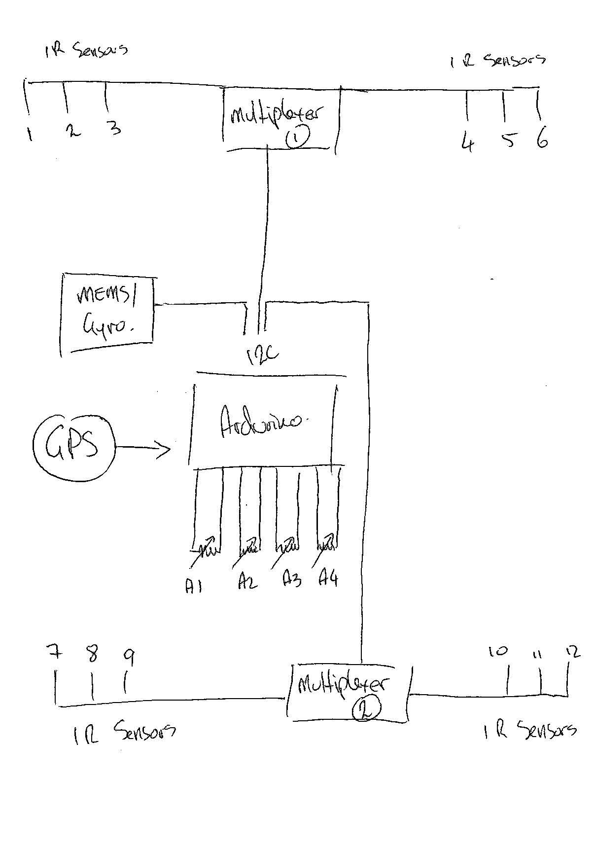
Basic layout as follows
Temp sensors:
- 3x 35deg FOV IR temp sensors for each wheel (MLX90614ESF-ACC) running on the i2c bus
- left and right wheels grouped into a bundle of 6 sensors managed by a local i2c multiplexer
- one multiplexer front and rear to give a total of 2 groups of 6 sensors (12 i2c IR sensors in total)
Suspension position sensors:
- 4x Analogue Bosch 0280122001 3 -Pin TPS sensors. Basically a 2kohm variable pot giving 0-5V output over 90deg sweep
Accelerometer/Gyro:
- again on the i2c, digital MEMS/Gyro from https://www.sparkfun.../products/11977
GPS
- haven't settled in this yet, but fairly standard 10Hz GPS
The i2c bus and the ADC channels can be logged at 100Hz, the GPS also logged at 100Hz but data only gets updated at 10Hz.
Possible issue is going to be running cable for the i2c temp sensors. As they're likely going to be 2m from the arduino, there's potential for signal loss, cross talk etc etc. need to get some good shielded twist Strand cable, and then there's weird sh*t about adding caps, different pull-up resistors, playing with baud rate and god know what that I don't understand. Plus... does having a multiplexer half way along the line essentially act as a relay post and reconditions the signal? Cuts the the wire distance effectively in half, so I assume there's less likelihood of signal issues?
Def worth having a crack though!
Edited by Doctor Ed, 20 October 2017 - 05:54 PM.
#755

Posted 20 October 2017 - 07:39 PM
#756

Posted 21 October 2017 - 08:48 AM
If you are using I2C for the communication between the parts and throughout the car then you probably have to make very, very sure it's extremely well shielded cable. I2C was never designed to work in 'noisy' conditions like cars (eg. ignition noise) and most transmission styles used on the bus have little to no error detection/correction so it's easy to get garbeld data or lose the packet sync.
As a proof of concept or initial version, I'd say go for it!
But you may in a second revision want to move the physical data transmission to something like a CAN connection that was designed to work in such conditions and may be more robust in the long run. No need to implement the whole data suite on top of it, just (ab)use the basic CAN transmission technique of using balanced wires and error control ![]()
Bye, Arno.
#757

Posted 21 October 2017 - 11:46 AM
#758

Posted 21 October 2017 - 11:57 AM
Edited by Doctor Ed, 21 October 2017 - 11:57 AM.
#759

Posted 21 October 2017 - 12:17 PM
#760

Posted 30 October 2017 - 07:54 AM
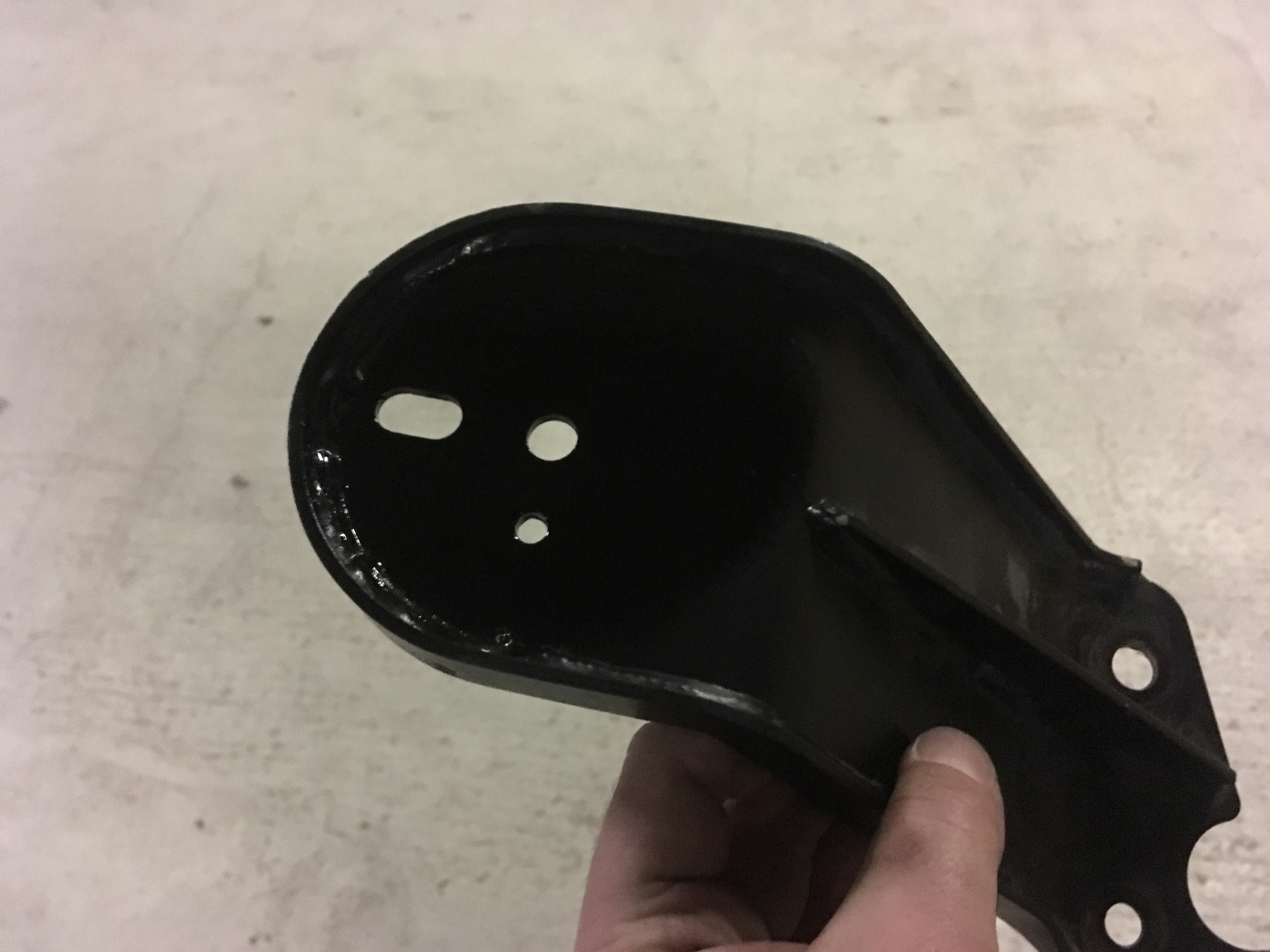
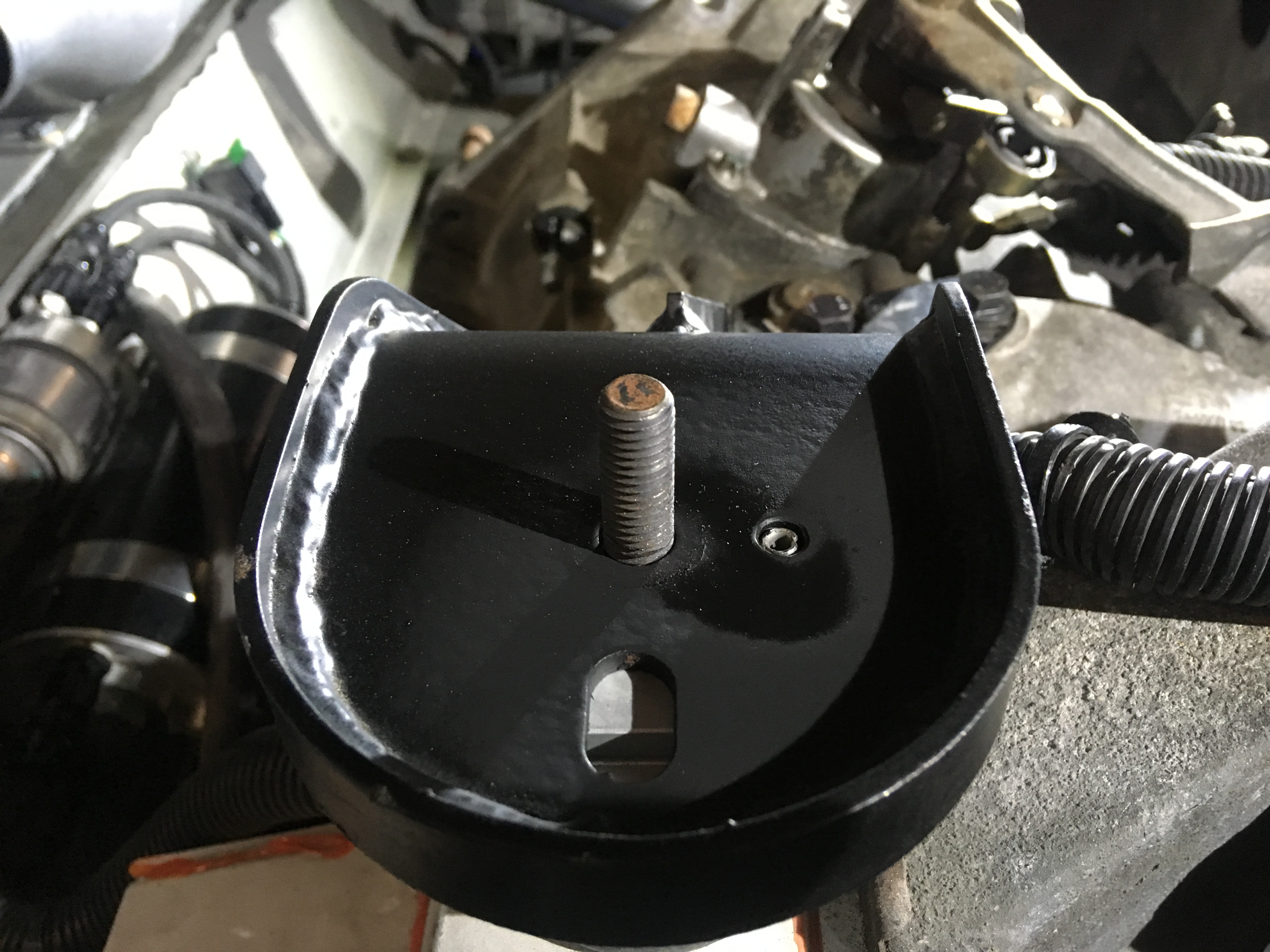
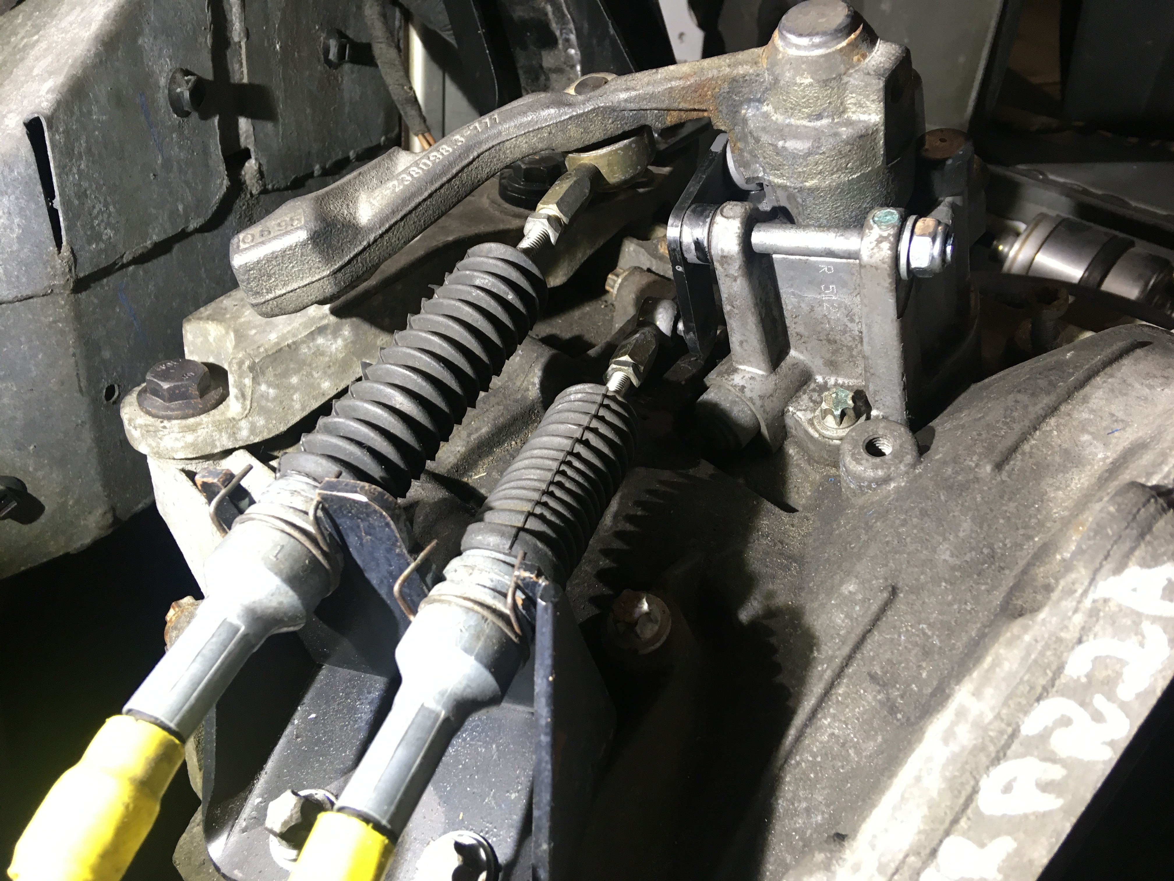
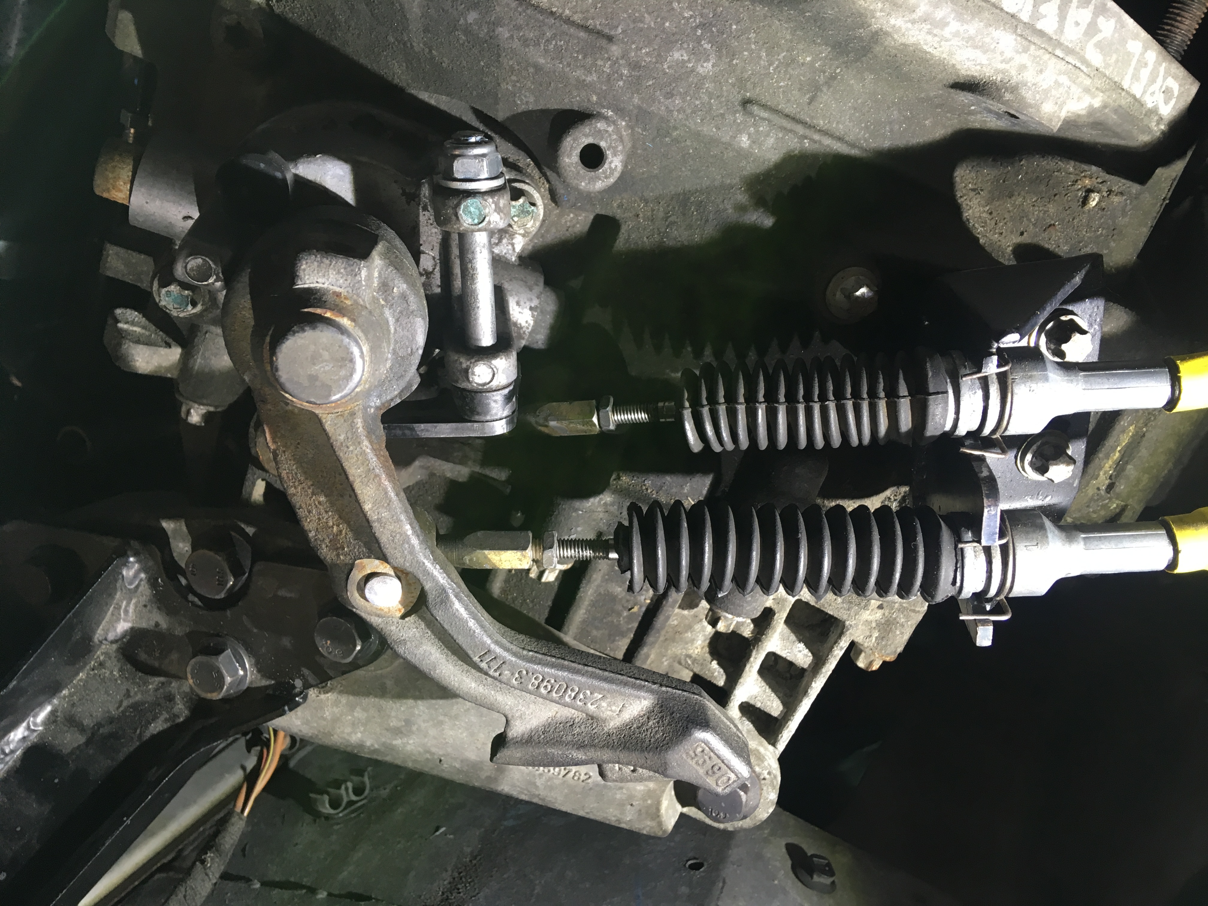
And the M32 inverted RWD selector assembly all finished. Lubed up the cables with graphite spray (evil stuff). Slippery fuckers now
1 user(s) are reading this topic
0 members, 1 guests, 0 anonymous users


