Project Fracas - 6Sp A20Nft
#1001
Posted 19 August 2018 - 10:59 AM
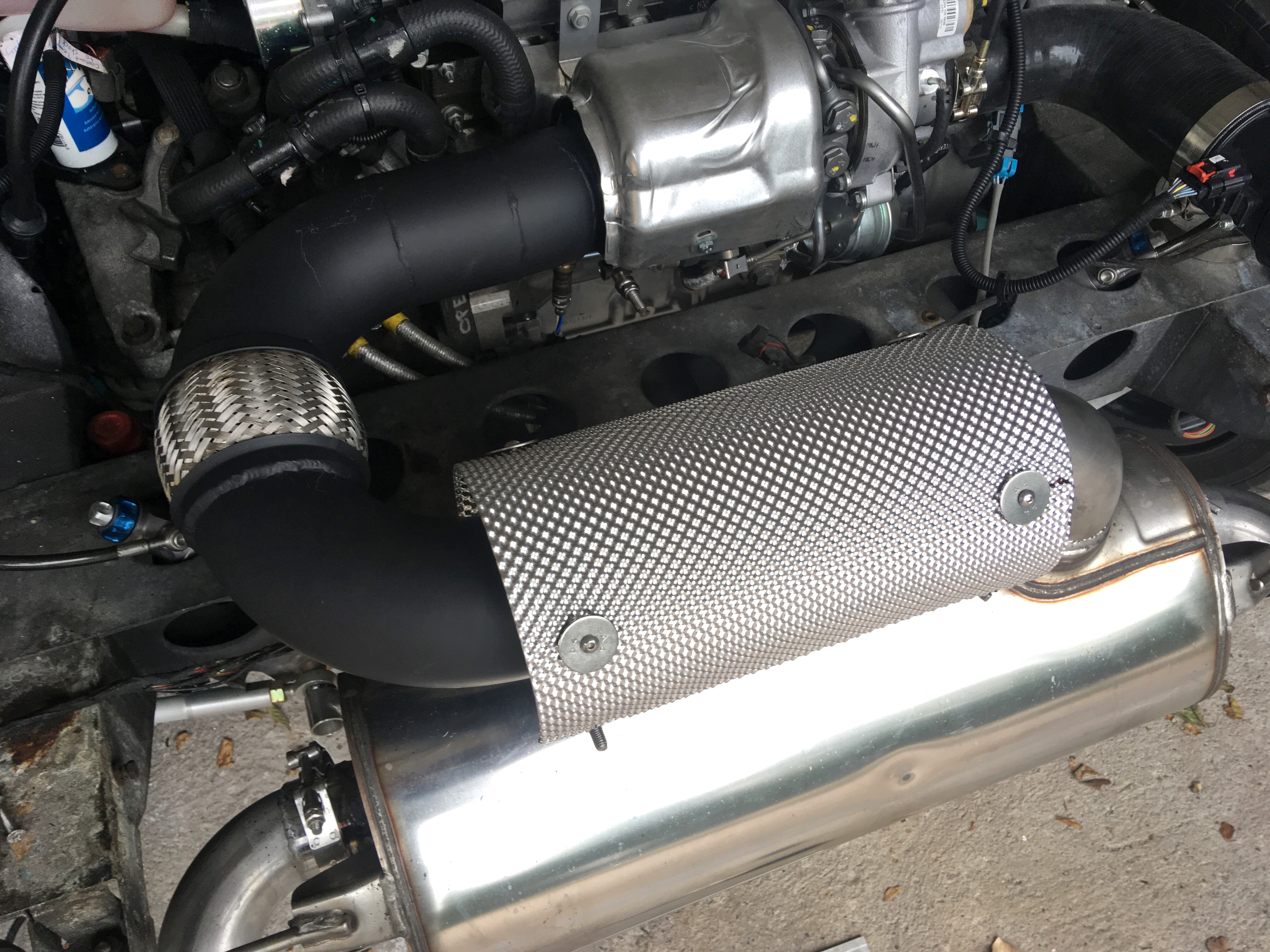
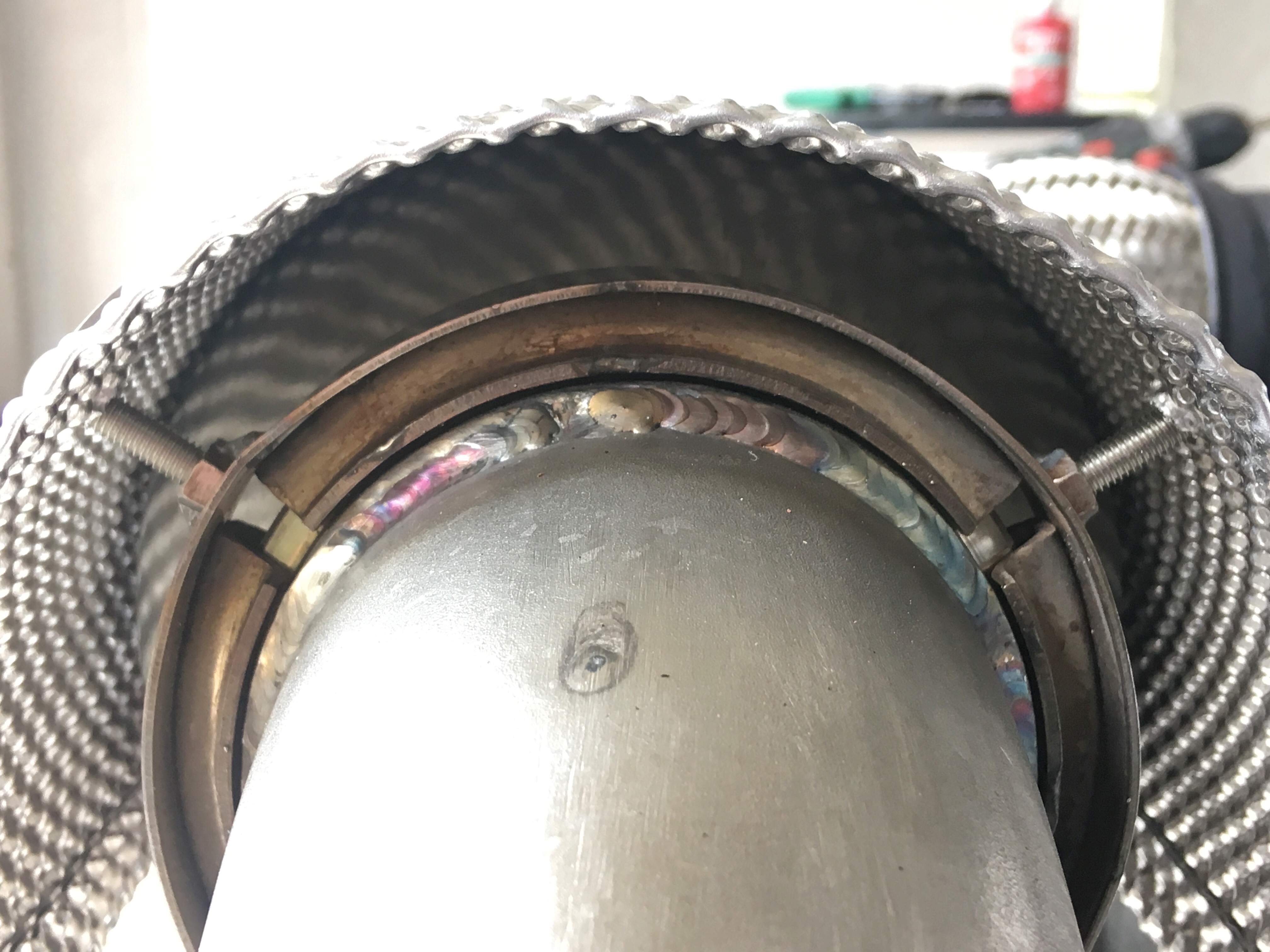
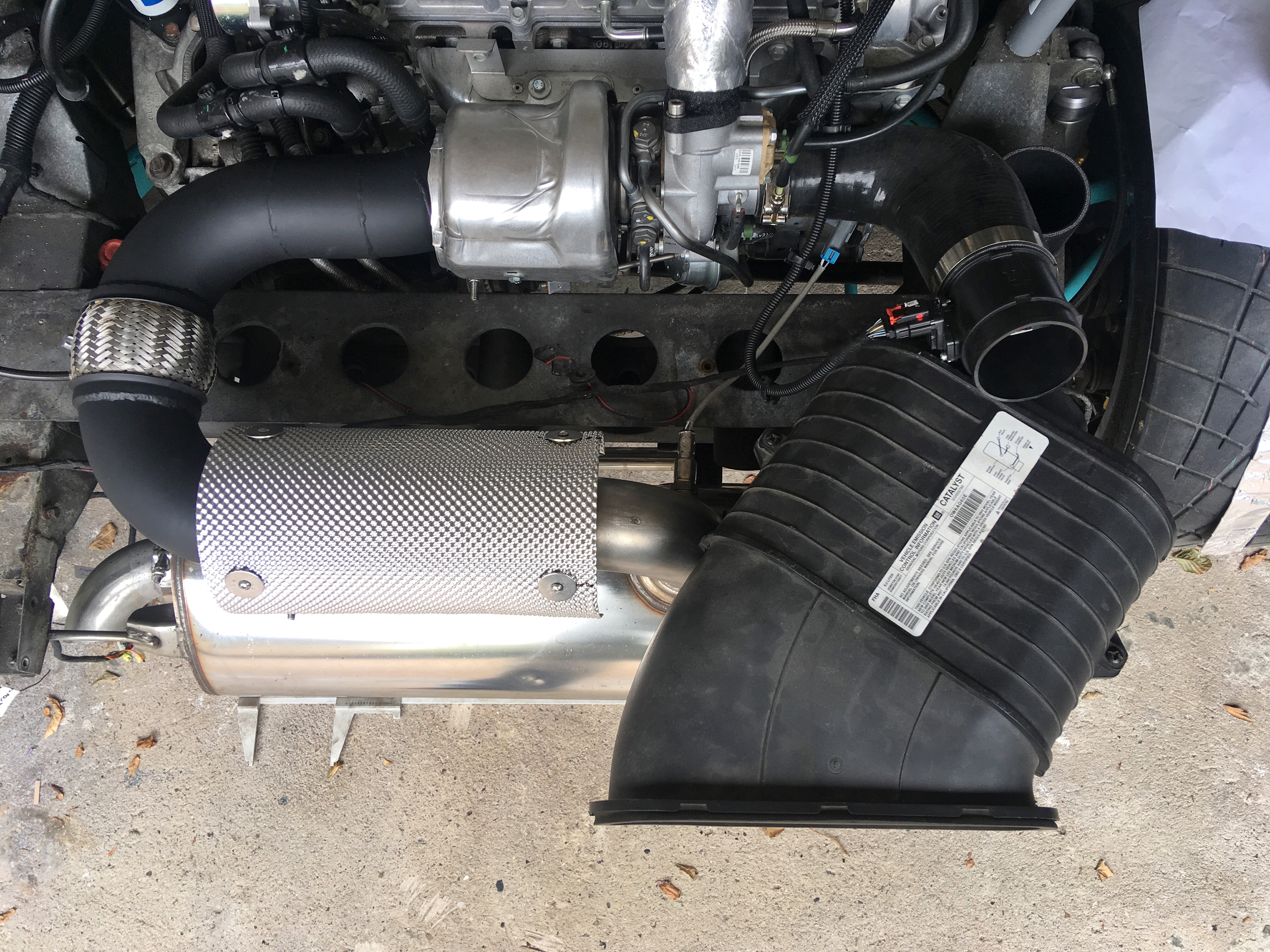
anyhoo... got some heat shield from carbuilders last time i was in aust. ACL stuff doesn't exist anymore it seems, but this is pretty damn good in comparison. double layered with a ceramic core. cuts, folds and forms well.
i welded some M5 nuts to the V-Band clamps on the cat, and will make some stand-off type bolts to suspend the shield around 5-10mm from the cat. i didn't have the right length bolts on hand, so at present its kindve sitting flush against the cat - just ignore that, it'll have a proper gap once i get some fasteners.
#1002
Posted 19 August 2018 - 10:59 AM
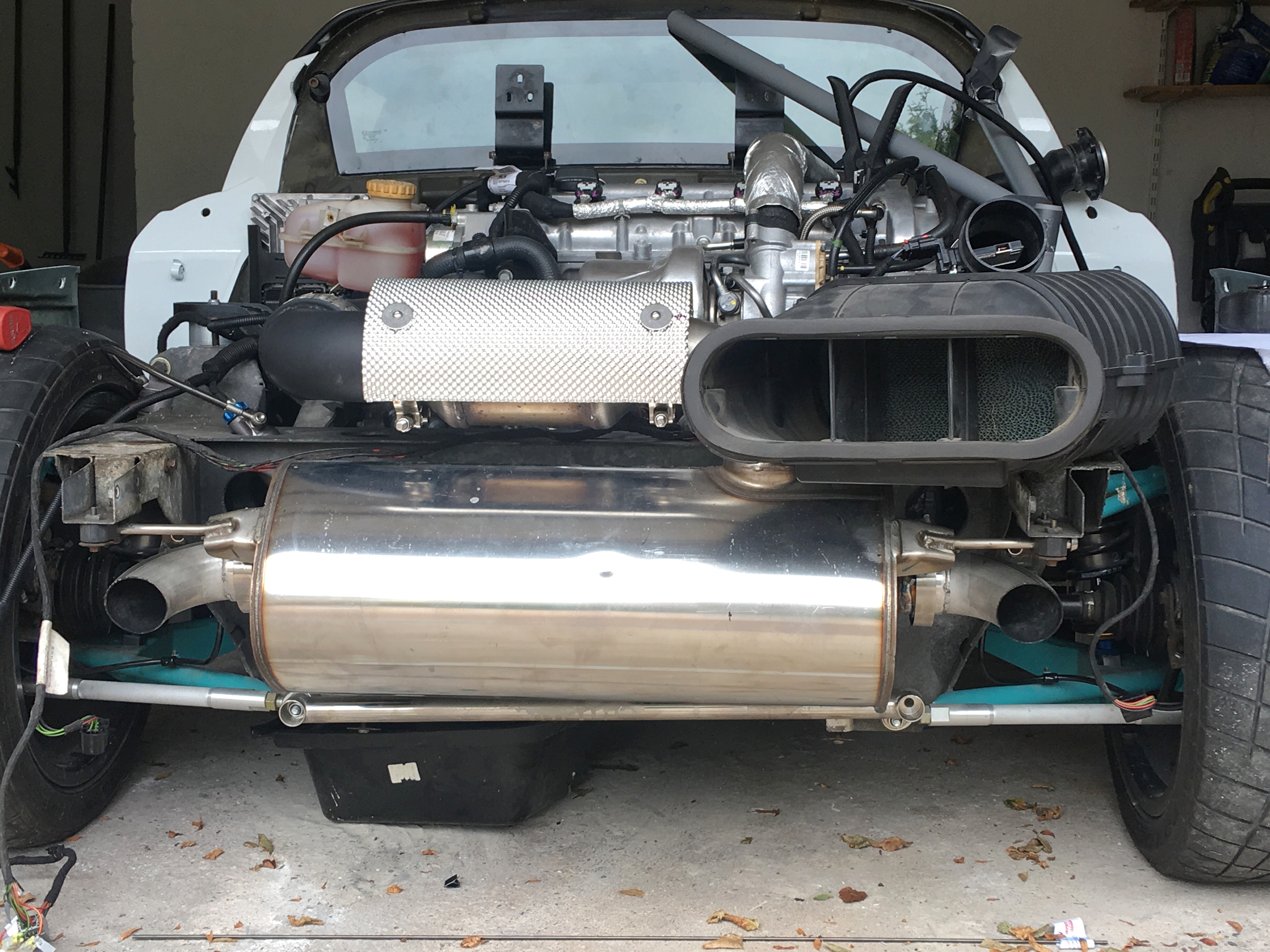
so cutting the mounts of the airbox, ive shoved it into place. its going to be close regarding the right side tail lights, but i think i can get it to *just* fit ok. the distance across the back between the inside edge of the inside pair of lights its about 800mm fwiw. how high the horizontal midline of the lights is... anyones guess at present. i think theres scope to move the filter a little higher, which will allow me to move it a touch further towards the midline. good that ive got lots of heat shield left over. pipework will be interesting too. hummer outlet fitting is 107mm (!!) and MAF is 80mm. theres no standard reducer hose that does that, so will need to get creative.
#1003
Posted 19 August 2018 - 04:36 PM
Is it really a good idea to pull air from a low pressure area above the exhaust. Seems like a good way of re-introducing EGR
#1004
Posted 19 August 2018 - 05:22 PM
Also, low pressure isn't necessarily true. Turbulent, sure
Edited by Doctor Ed, 19 August 2018 - 05:24 PM.
#1005
Posted 19 August 2018 - 06:42 PM
i need to be smart with exhaust flow
#1006
Posted 20 August 2018 - 09:19 AM
pipework will be interesting too. hummer outlet fitting is 107mm (!!) and MAF is 80mm. theres no standard reducer hose that does that
Can get pretty close though...
http://www.hps-silic...nch-length.html
Bye, Arno.
#1007
Posted 20 August 2018 - 10:01 AM
Or if you don't mind a somewhat more industrial look https://www.voskunst...6882/
Will require some heat shielding, but in the intake tract no issues with pressure. You just want it to be air tight.
#1008
Posted 20 August 2018 - 06:15 PM
Edited by Nev, 20 August 2018 - 06:18 PM.
#1009
Posted 20 August 2018 - 07:37 PM
played around with the airbox too. getting a feed from the front is going to be a PITA.
Shame you can't utilise the sealed space inside the sill to get a cold air feed to the back by putting in a large hole front & back.
#1010
Posted 22 August 2018 - 10:15 PM
Now kicks on the first hit of the key, so a little rewarding, but fcuk me dead
#1011
Posted 23 August 2018 - 08:58 AM
Perhaps teaching you to suck eggs, but if you are talking about the ground points on the chassis front and back then the rivnuts are not part of the ground path and the orignal ones used should be (black) insulated ones.
The original grounding setup on the chassis beams is as follows:
With the special alu stepped washer contacting around the rivnut on an area of the chassis where the anodisation has been ground off by the factory.
This also provides the required contact area for the current transfer. The rivnut should only provide the fixation but not really be part of the current path.
Issue can be if the rivnut gets loose or pulls up through the base that the whole 'stack' of washers no longer clamps down hard onto the section of chassis beam where the anodisation is removed and that gives an intermittent/bad ground.
Bye, Arno.
#1012
Posted 23 August 2018 - 09:22 AM
Things you learn having started with only a naked chassis
Ah well. New rivnuts with much metal contact and superb conductivity now insitu. Stepped washer thing would be good to support current flow. Anyone have one/two?
Edited by Doctor Ed, 23 August 2018 - 09:24 AM.
#1013
Posted 23 August 2018 - 10:08 PM
#1014
Posted 24 August 2018 - 04:03 PM
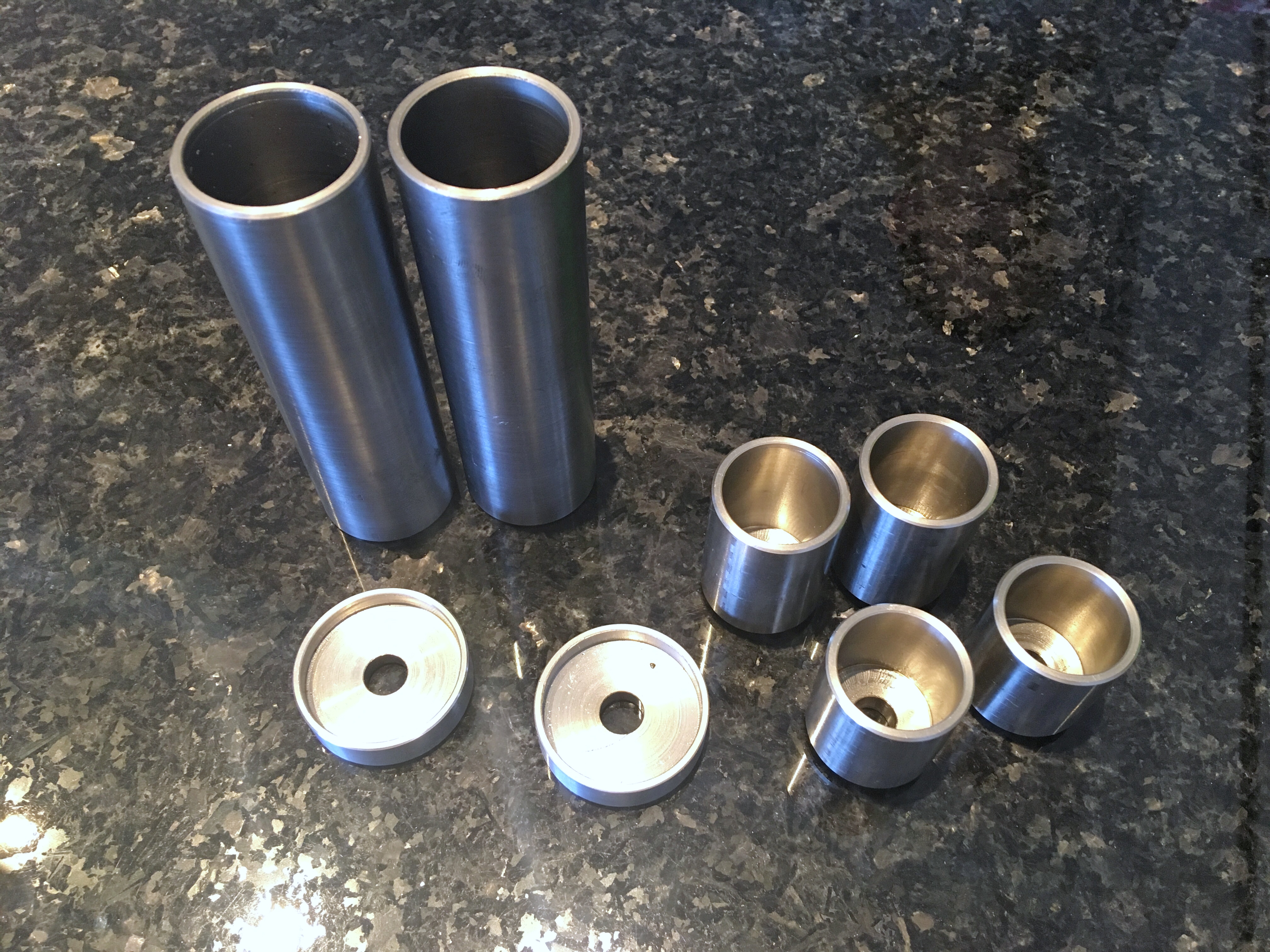
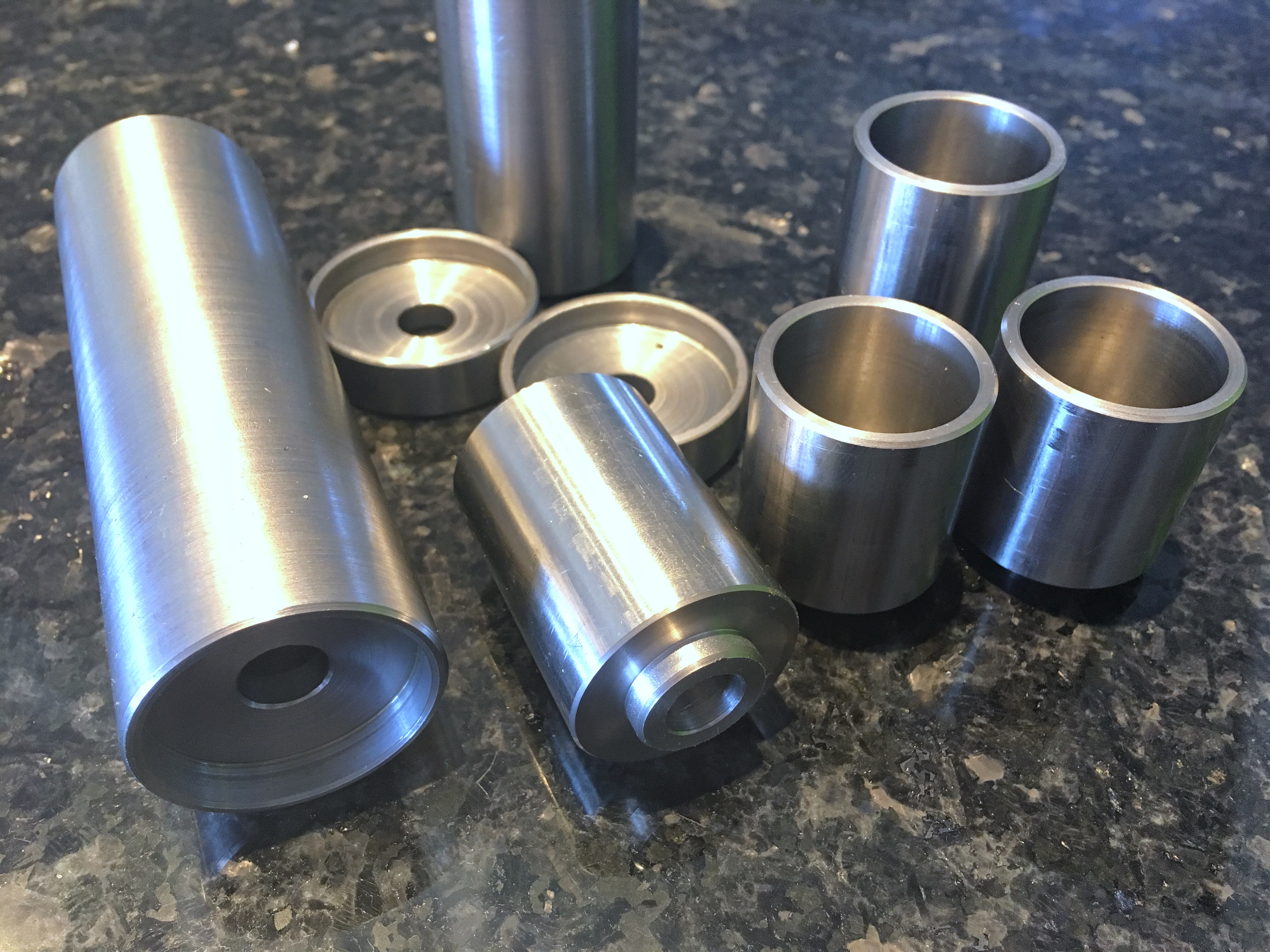
First I needed to tackle the anchors/mounting points which use a variety of locating shoulders and/or stand off shoulders to seat against rose joint bearings etc, and needed to get these bits machined in one pice to spec. Lo and behold, found a gumtree add from some retiree doing lathe work from home for cash... €80 and 4days later the post arrives today with my 8 finished parts in perfect tolerance. Holy sh*t! I've saved this guys details. I almost want to find more stuff that needs to get made just so I can engage his services again!
#1015
Posted 24 August 2018 - 08:25 PM
#1016
Posted 24 August 2018 - 08:58 PM
I need a lathe
#1017
Posted 25 August 2018 - 11:51 PM
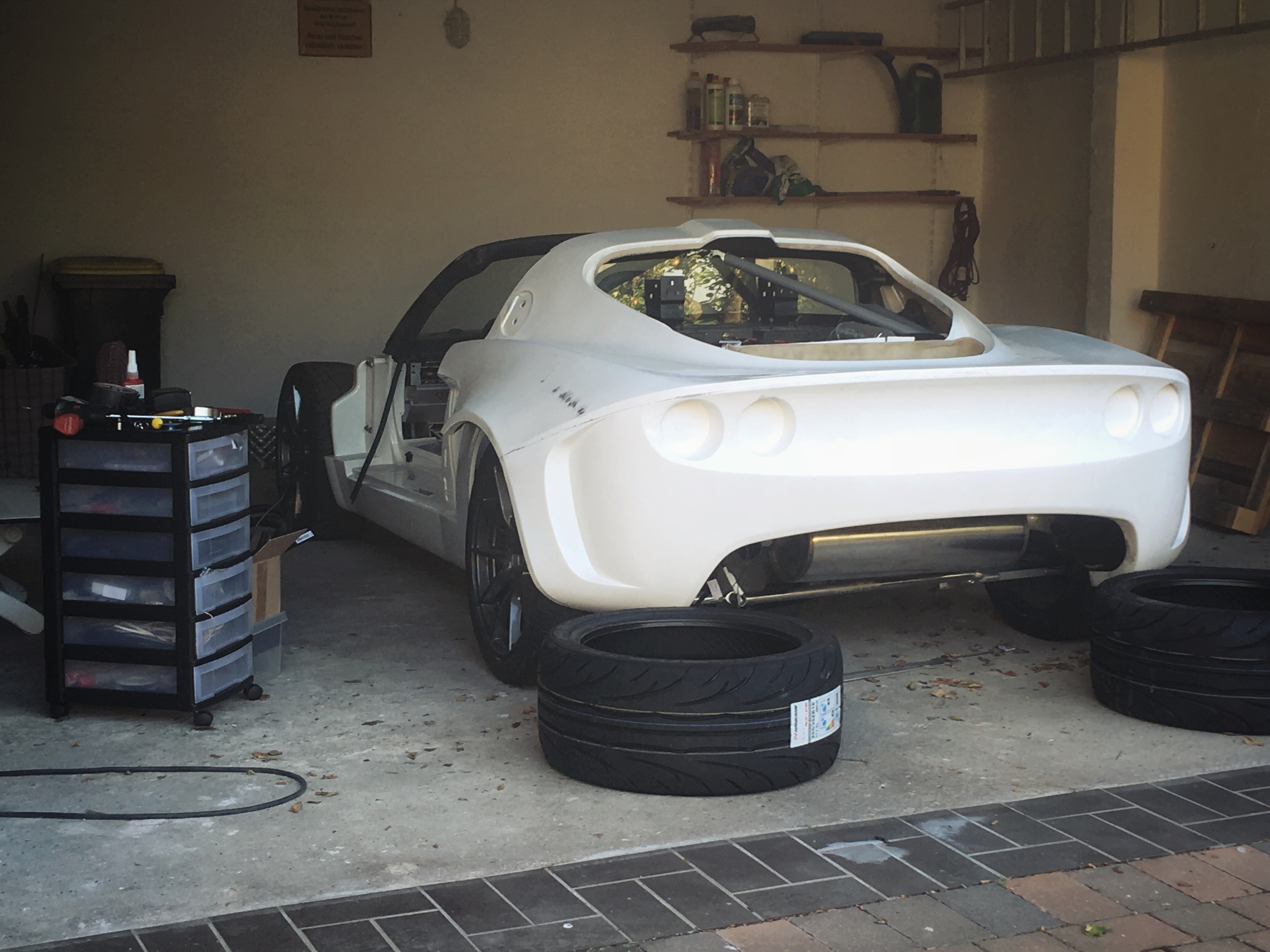
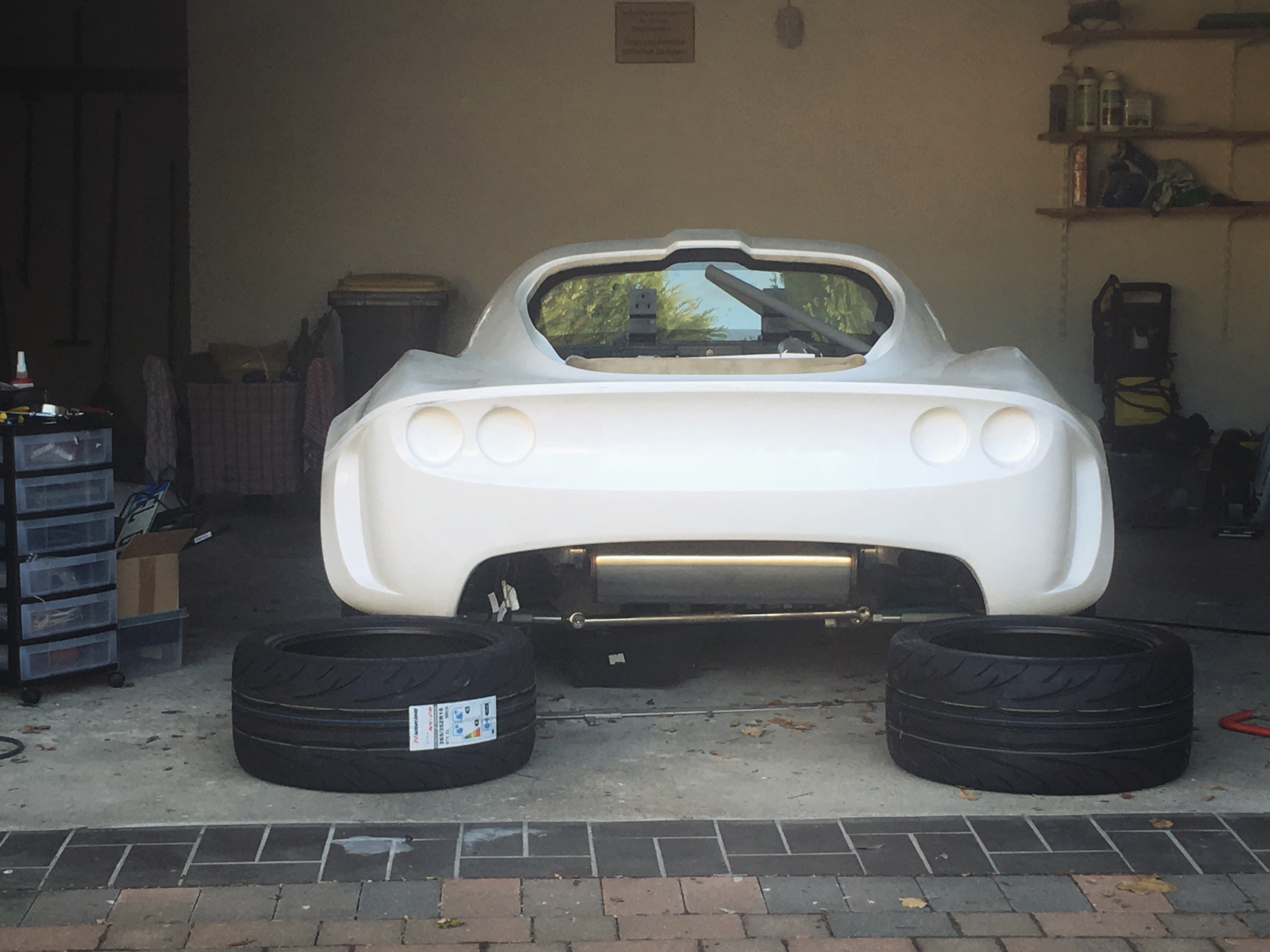
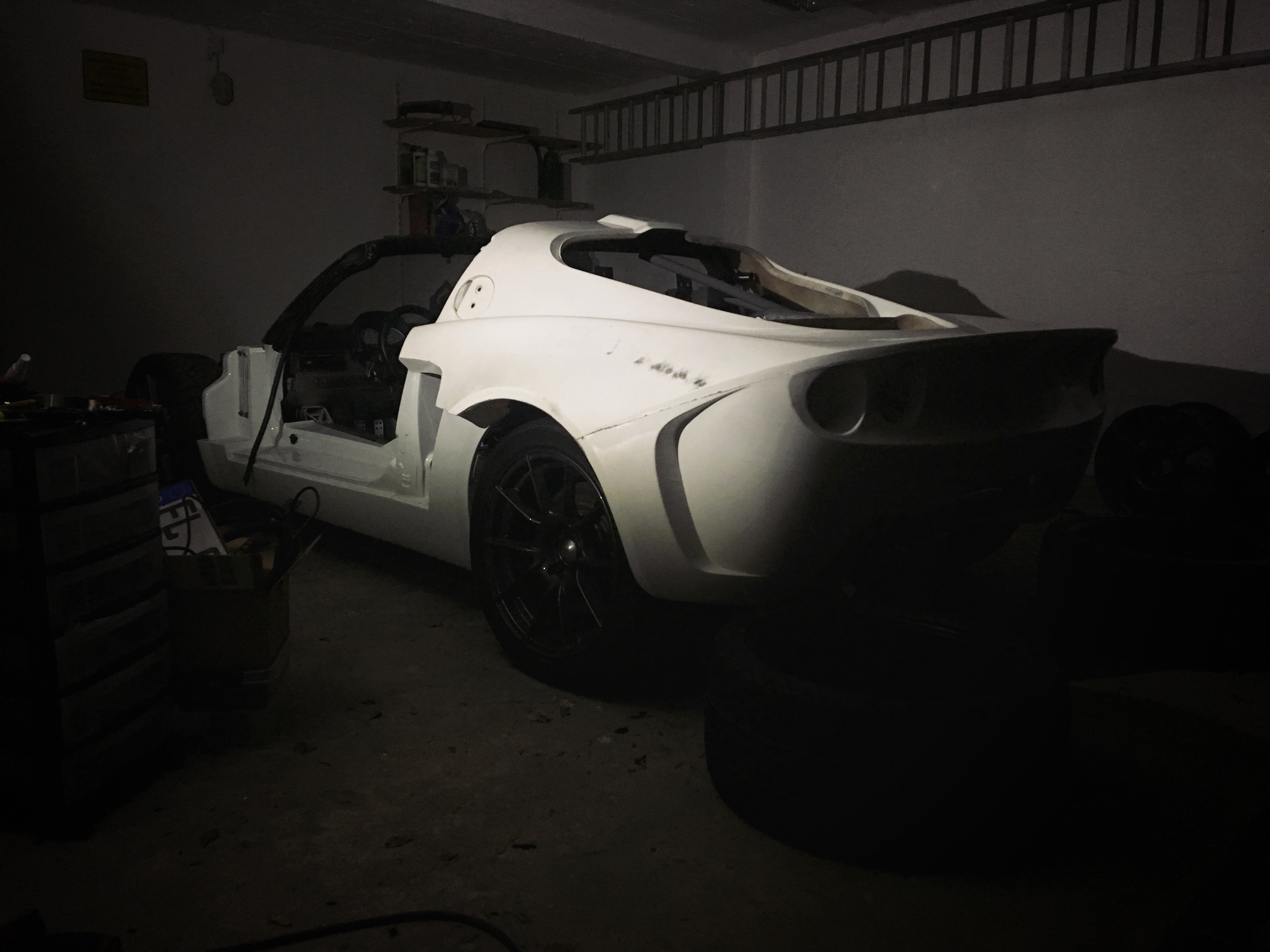
thought it was time to bring the bodywork back into the picture, and start measuring the final location of things to make sure tab A fits into slot B without any major fuckups
so on with the measuring:
rear camber is sitting presently with zero spacers at -2.6deg (thanks garvice!) resulting in a 20mm difference in offset measured between the top and bottom of the 17" rim
measured clearance at the top of the rim to the outside edge of the middle of the clam arch with current 9.0 x 17 ET20 rims = 70mm
calculated clearance top of the rim to the outside edge of the middle of the clam arch with 10.0 x 18 ET35 (no offset spacer) = 72mm
allowing a bit of tuck to allow for less camber, tyre size, and allowing for the fibreglass arch return, lets say a tuck of 15mm measured at the upper rim edge (about 19mm if measured at the top of the tyre), leaves a spacer requirement of 72-15 = 57mm. round that up to say 60mm (come on, better flush than tucked!) and oooh, hello... https://spurverbreit...er&typ=E00TARGA lets order 2 of those then :yup:
265 Nankangs NS2Rs (actual width 271mm) are getting fitted on monday on the 18's, so give it a little while and we'll have some proper wheels mounted to this thing and see how it looks
regarding the clam itself - the symmetry and fit is actually pretty damn good. im quite impressed. theres a little bit of twist and spring in it, but maybe only 10-15mm across corners just sitting roughly unsupported. a couple of actual solid mounting points will pull it down to within a couple of mm.
currently ive got it sitting: with ground clearance measured at the rear chassis at 130mm (rear aluminium chassis rail), the front horizontal panel join line of the rear clam sits at 595mm to the floor, and the lowest rear edge of the rear wheel arch sits at 200mm (midline of the toe link fasteners). things that look like they should be horizontally level, according to my spirit level, are. this all give a 290mm distance from the most rearward subframe flat surface to the underside of the clam.
the air filter fits well too without fouling too much stuff. its close, but not too close to the last turn of the dump into the muffler, and nothing a bit of heat shield won't take care of. its kindle neatly packaged actually. exhaust tips im currently thinking ill turn down into the outer channels of the diffuser, and turn them into the underbody flow coanda style. need to make sure the carbon doesn't catch fire, but im on it.
going to find the vertical midlines of the arches and wheel axels tomorrow, and start working out the chop-suey line
#1018
Posted 25 August 2018 - 11:52 PM
#1019
Posted 26 August 2018 - 12:22 AM
are you going full s2 now then?
#1020
Posted 26 August 2018 - 07:43 AM
Edited by Doctor Ed, 26 August 2018 - 07:44 AM.
8 user(s) are reading this topic
0 members, 8 guests, 0 anonymous users