Jump to content


Photo

Project Fracas - 6Sp A20Nft


  • Please log in to reply
1268 replies to this topic

#1201 Doctor Ed

Doctor Ed

    Need to get Out More

  • PipPipPipPip
  • 1,188 posts
  • Location:Germany

Posted 06 June 2019 - 08:03 PM

Max angle I’ve mentioned somewhere back a bit, without looking i think it was 28deg

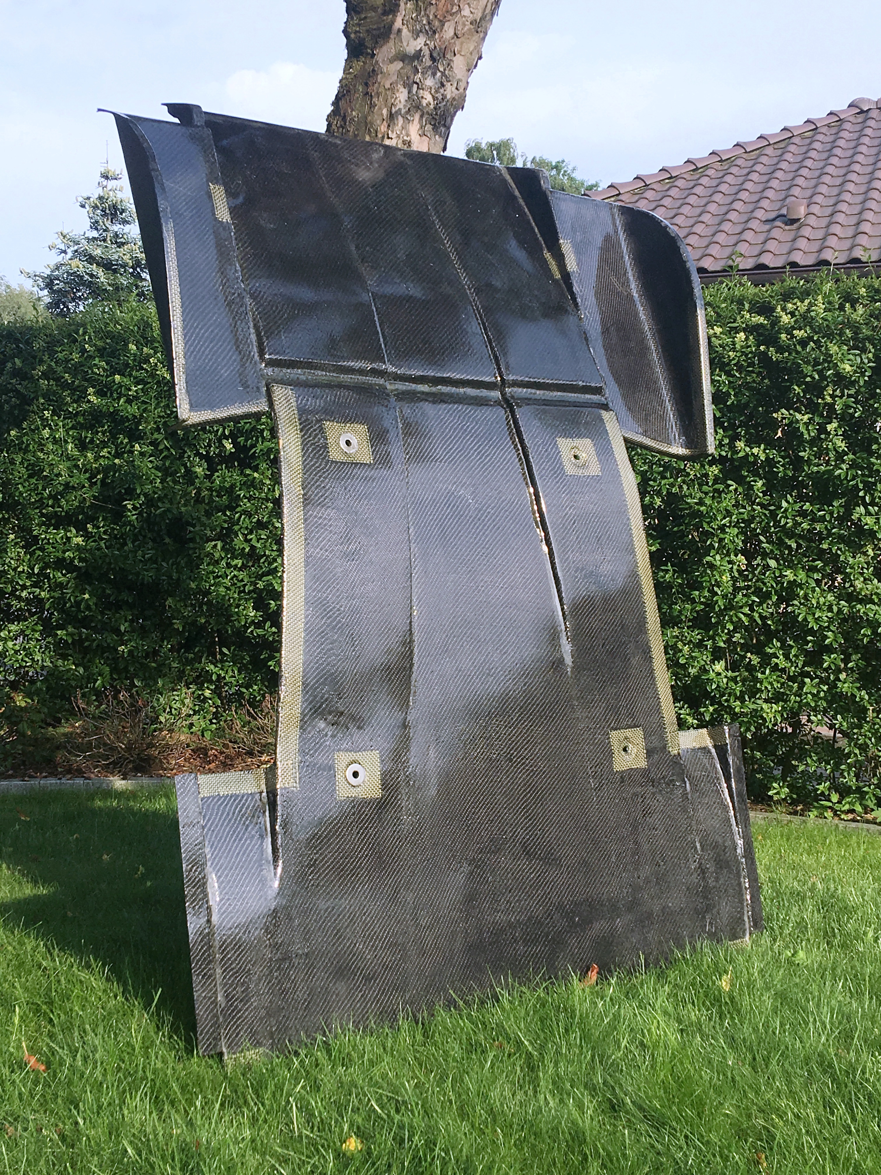
Data shows curved diffusers tolerate bigger angles. The bigger angles also generate more downforce in situations of larger ground clearance. So altogether fits well for the design and use of this car :)

Also finish up the laminate yesterday, added a further upper carbon layer to bump the overall stiffness up a notch. Now remarkably strong :)

6.8kg

5 layers 2x 200cf, 1x 225csm, 1x 200cf, 1x 240cf. Reinforcement patches on stress points

Not super lightweight, but respectable for its size. And it’s tough as fcuk.

IMG_6751.JPG

Edited by Doctor Ed, 06 June 2019 - 08:04 PM.


#1202 Doctor Ed

Doctor Ed

    Need to get Out More

  • PipPipPipPip
  • 1,188 posts
  • Location:Germany

Posted 08 June 2019 - 07:11 PM

so picking back up on the BFW again...

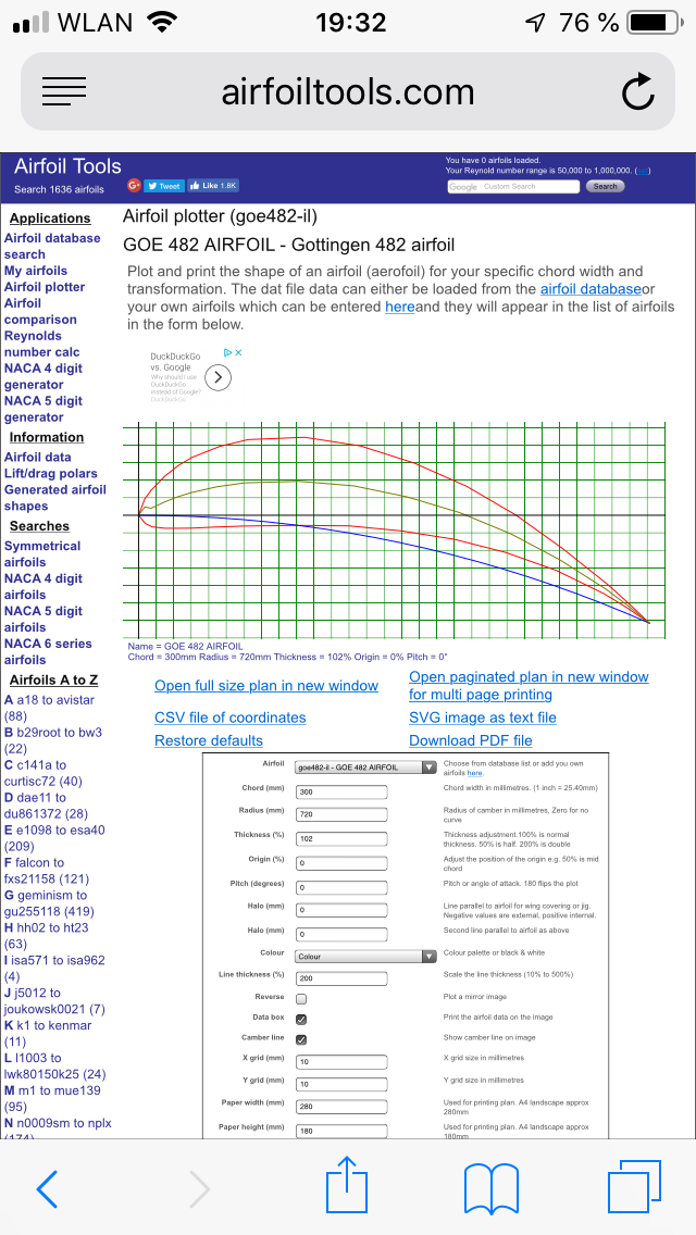
sketched up a modified GOE482 Airfoil

IMG_5685.PNG

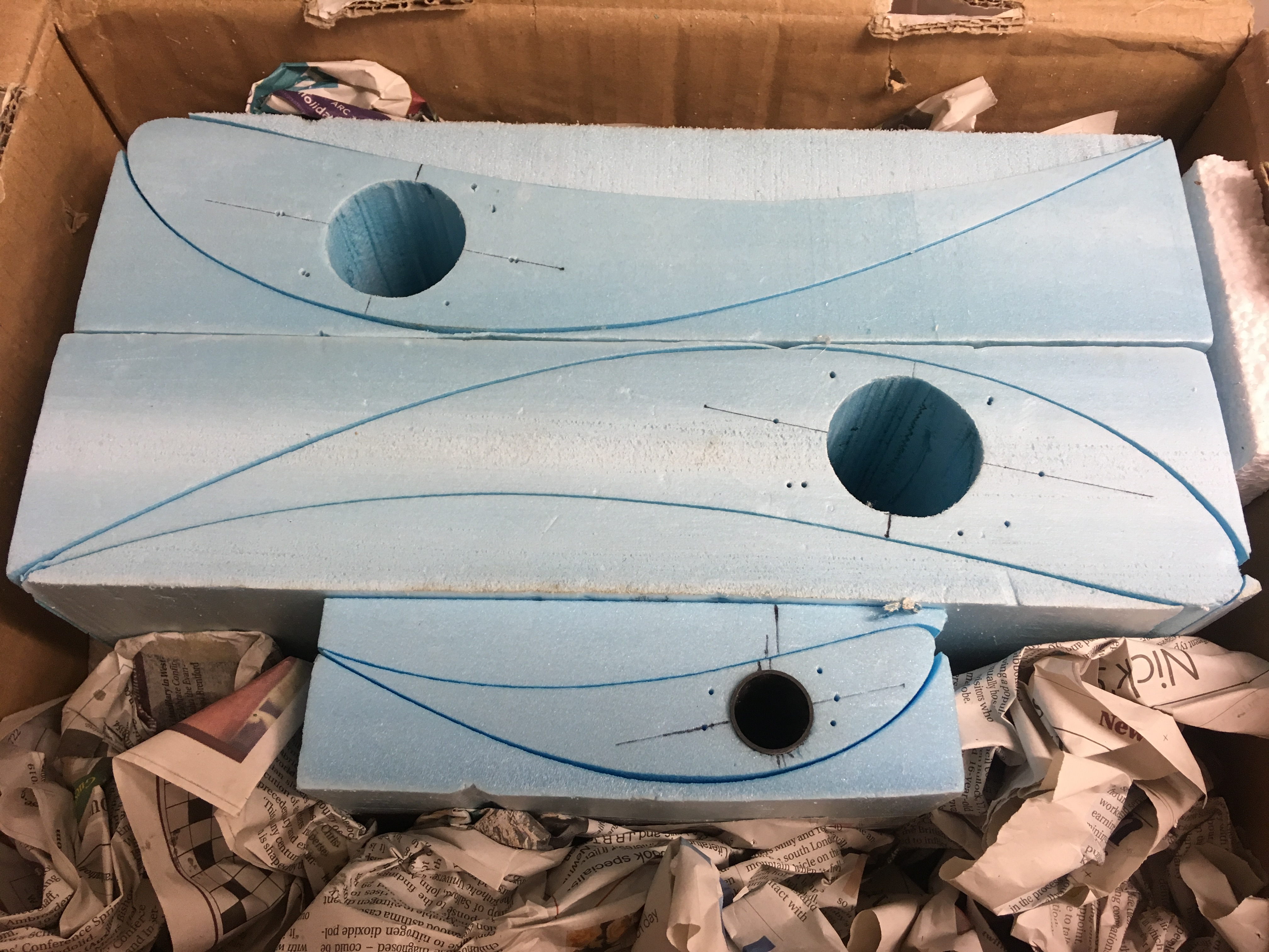
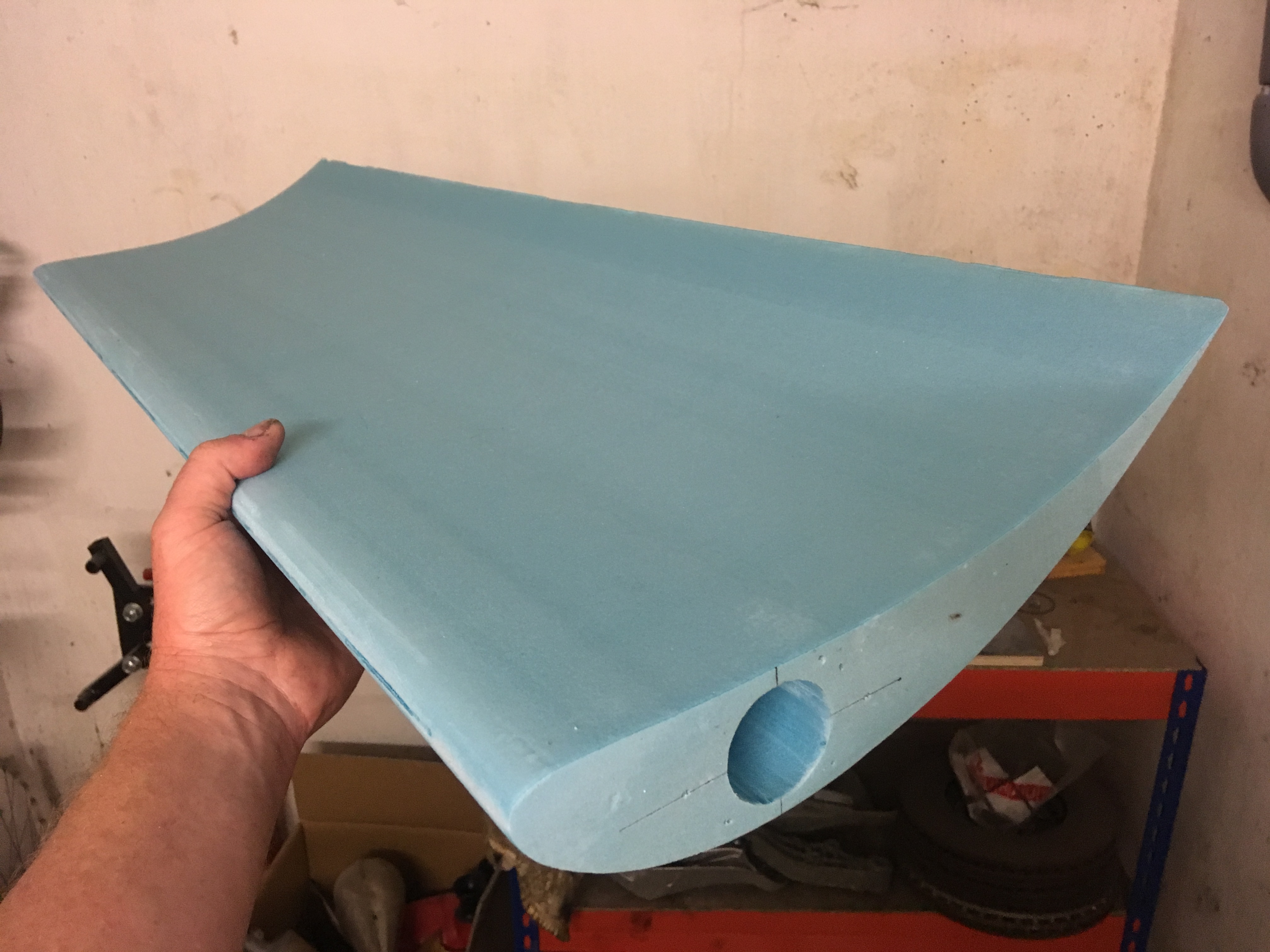
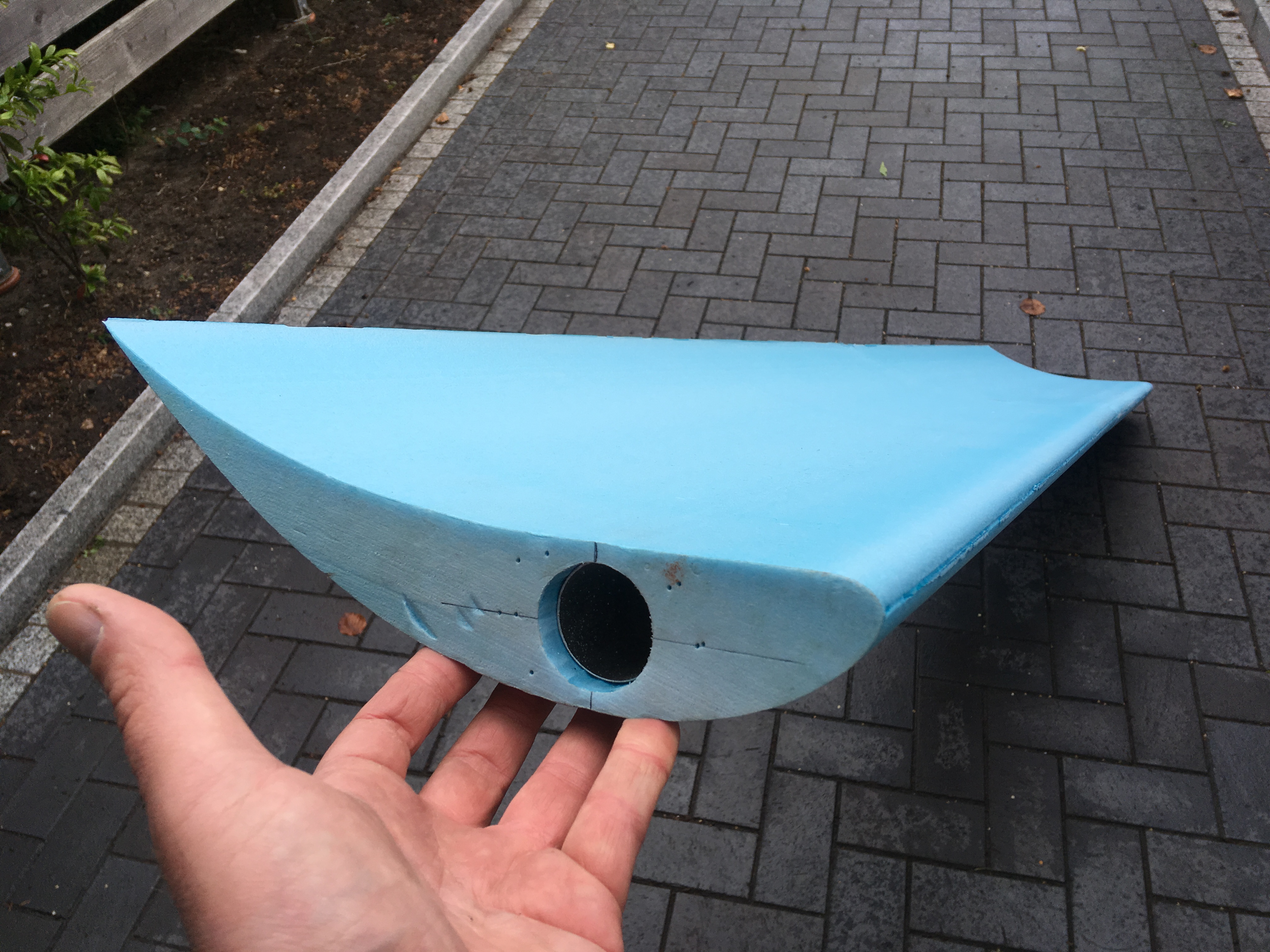
sent the CAD of the airfoil off to a bloke in the UK who makes CNC hot-wired RC model wing cores. had a choice of foams, and went for a middle density open cell. slightly heavier, but as i also wanted to use the female cut parts to prep as moulds, i figured the higher density would work well to sand and finish to a good surface.

IMG_6500.JPG

IMG_6502.JPG

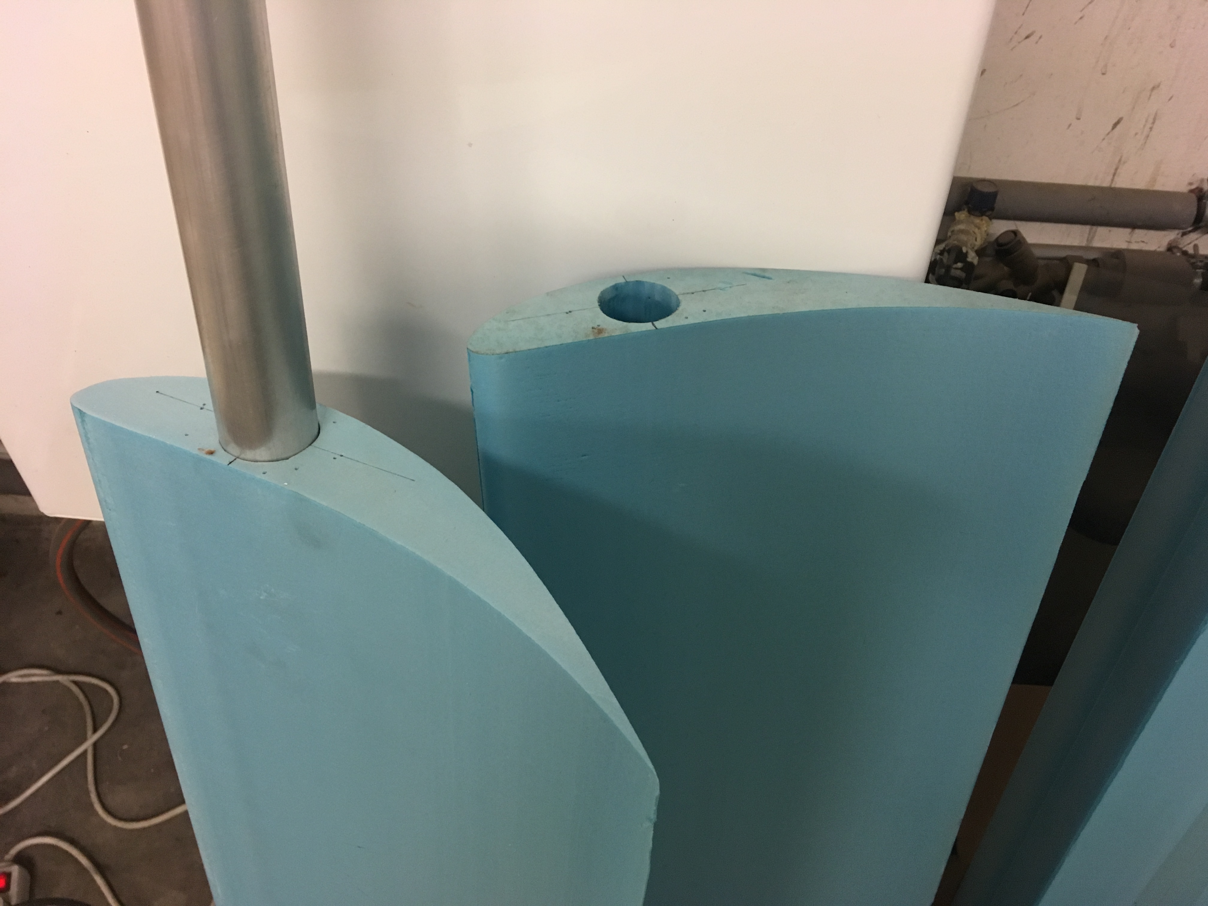
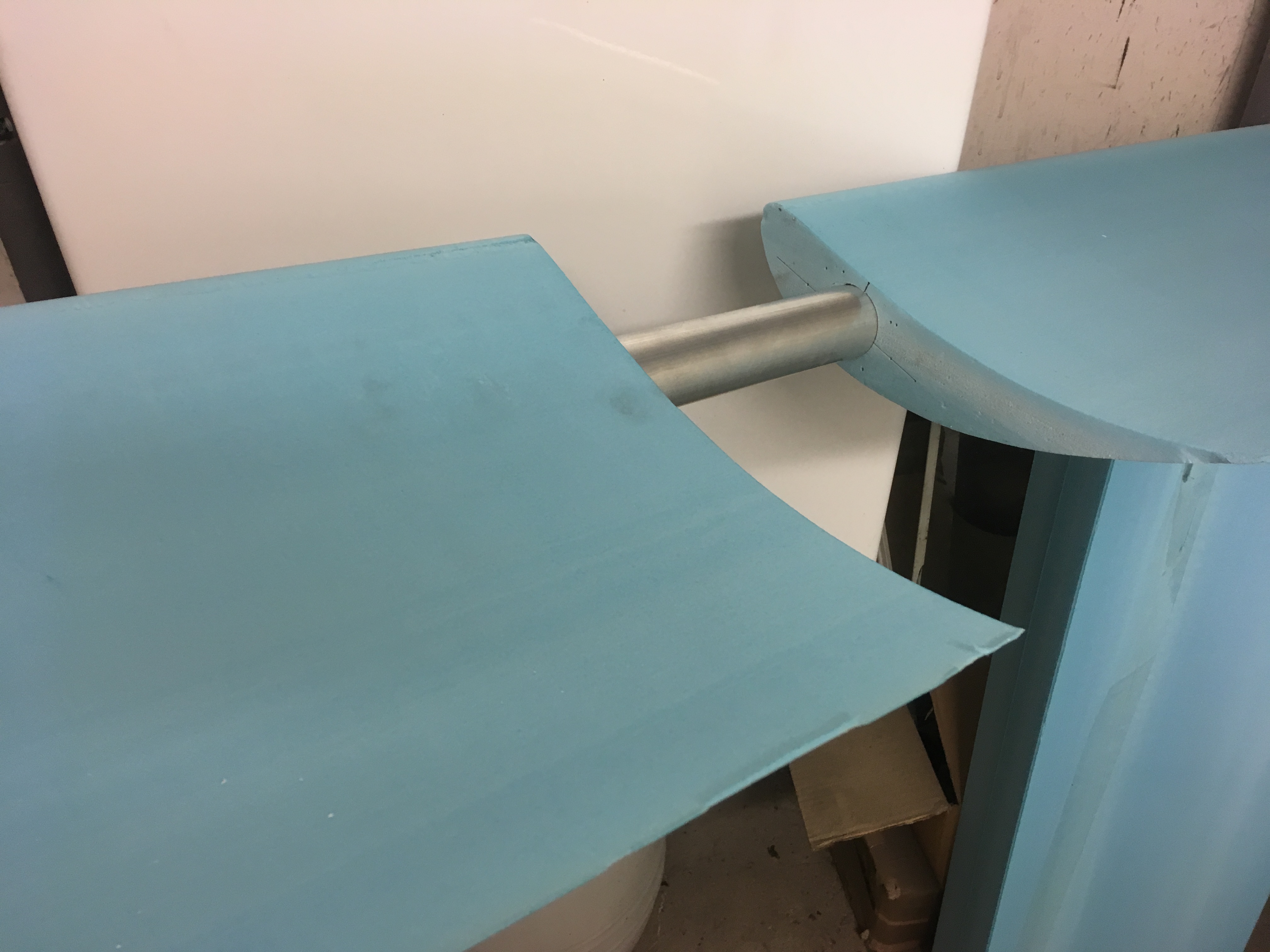
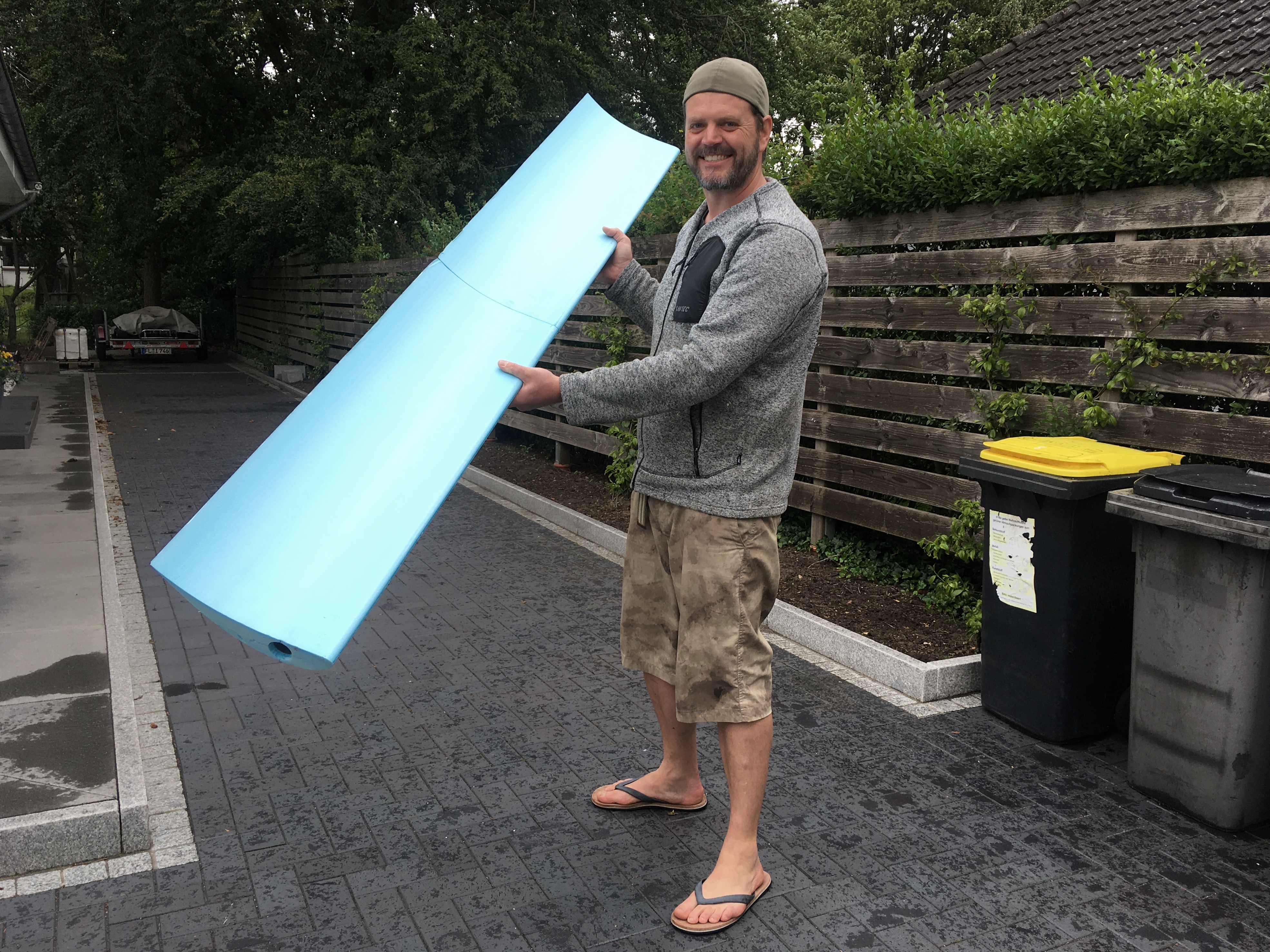
maybe a little paranoid, but i had the cores cut with a central hole for a full length spar. as i got the cores cut in 100cm length, it also gave me something reliable and fixed to mount the 2 halves together into one massive solid span.

for the 310mm chord i went with a 40mm dia spar, then spent a while umming and ahhing what i was going to slide in there. a nice 200cm long carbon tube would be nice, but in 40mm are fcuking expensive. so went with some 40x1.0mm aluminium tube. relatively light, wayyy cheaper than carbon tube, and little more forgiving. though to be honest once skinned in CF, any benefit of some flexibility of the aluminium is going to amount to about naught.

so yeah, slid the fuckers together (very tight fit over 100cm in both directions is a bitch to do carefully not otherwise fcuking the foam cores) and happy days. worked out well.

now i need to sit down and mount the negative parts to some plywood, somehow prep them as a mould, flow coat/release agent them etc. I've had some practice now, this will be the test ;)

IMG_6757.JPG

IMG_6759.JPG

IMG_6762.JPG

IMG_6765.JPG

IMG_6766.JPG

IMG_6770.JPG

#1203 Doctor Ed

Doctor Ed

    Need to get Out More

  • PipPipPipPip
  • 1,188 posts
  • Location:Germany

Posted 09 June 2019 - 02:02 PM

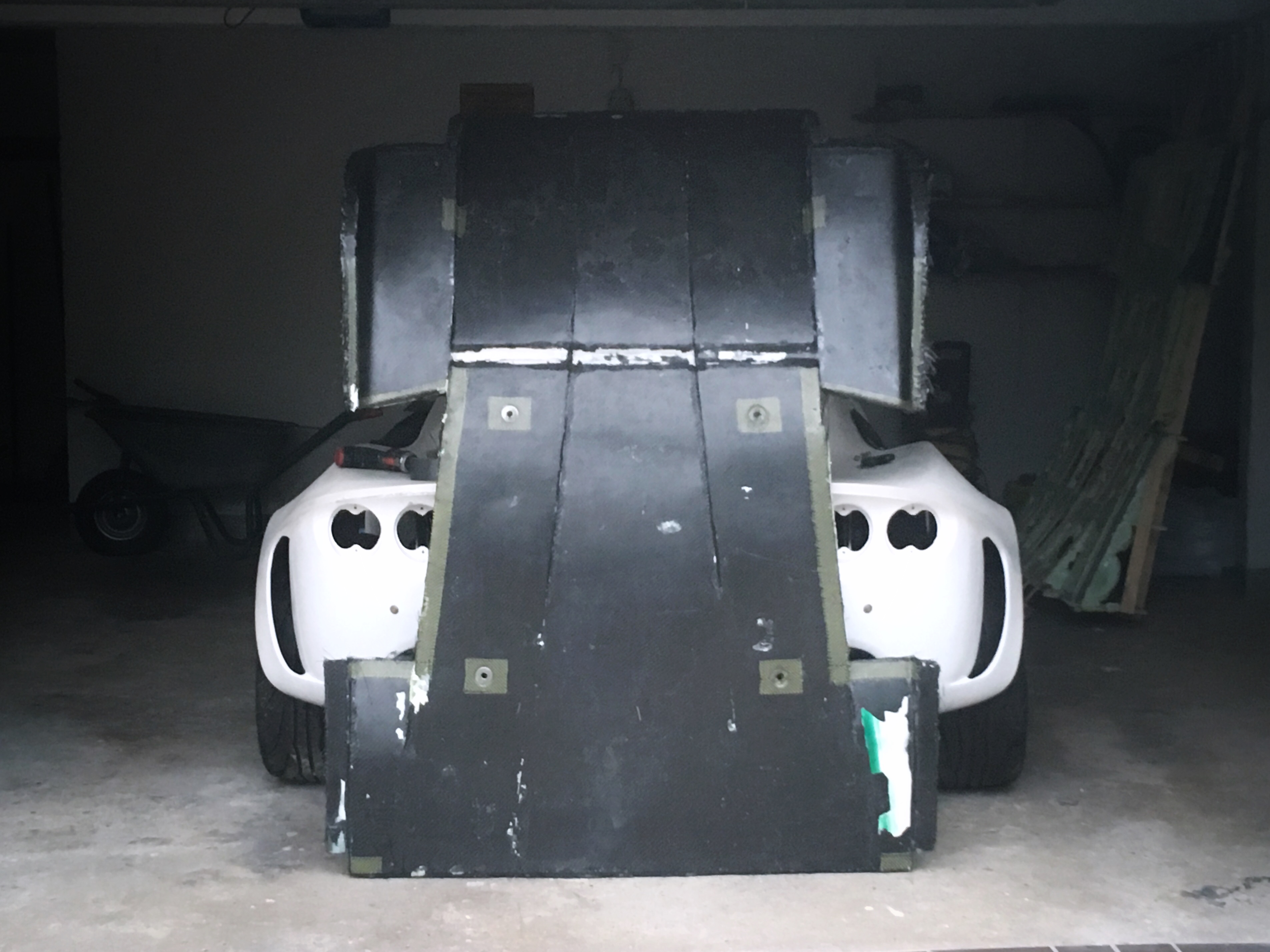
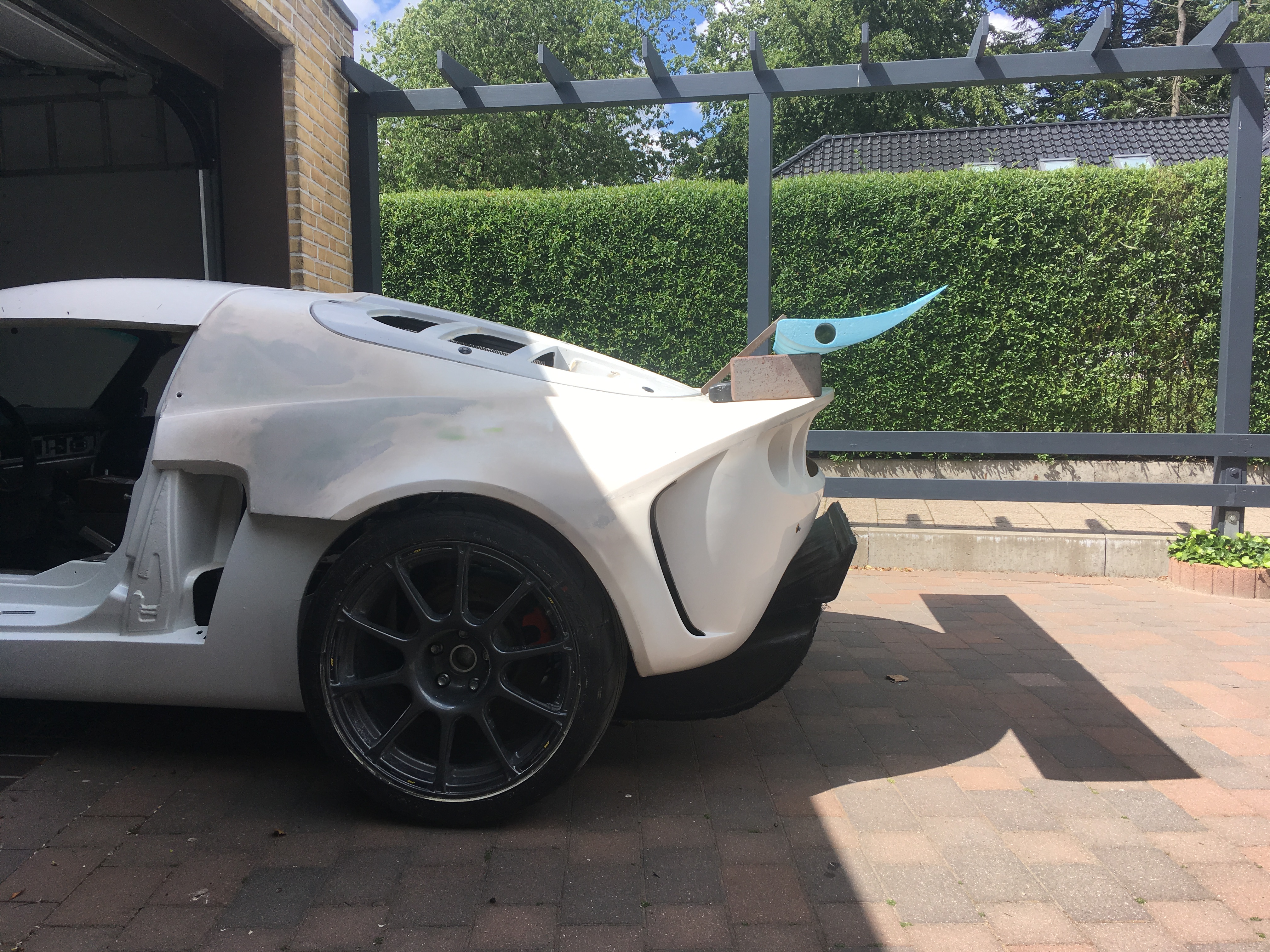
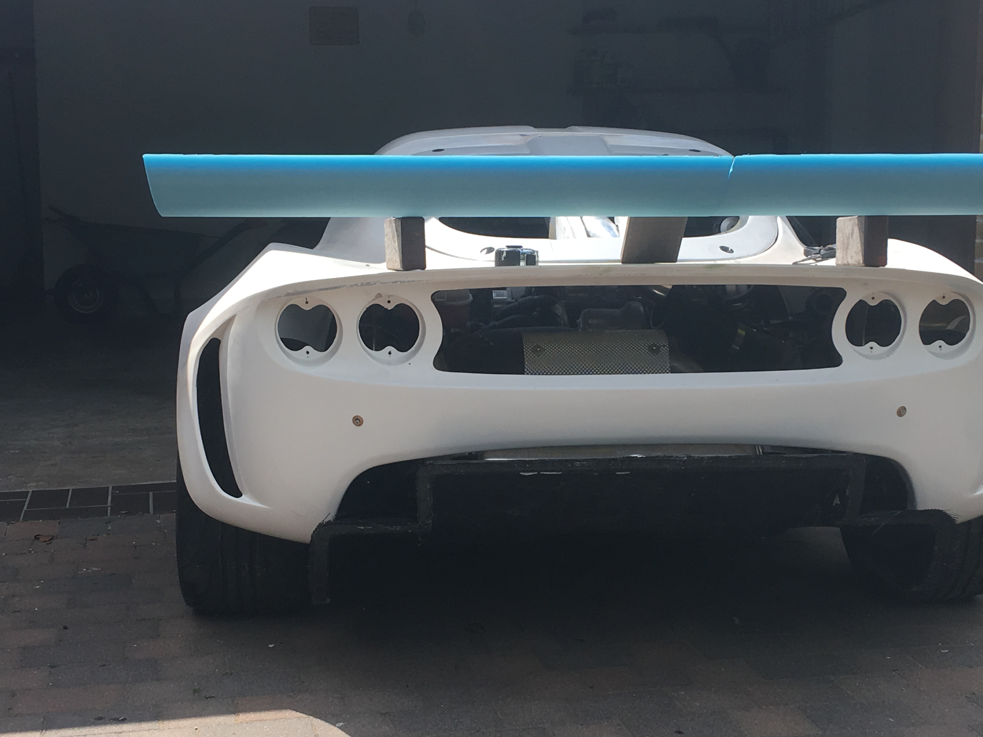
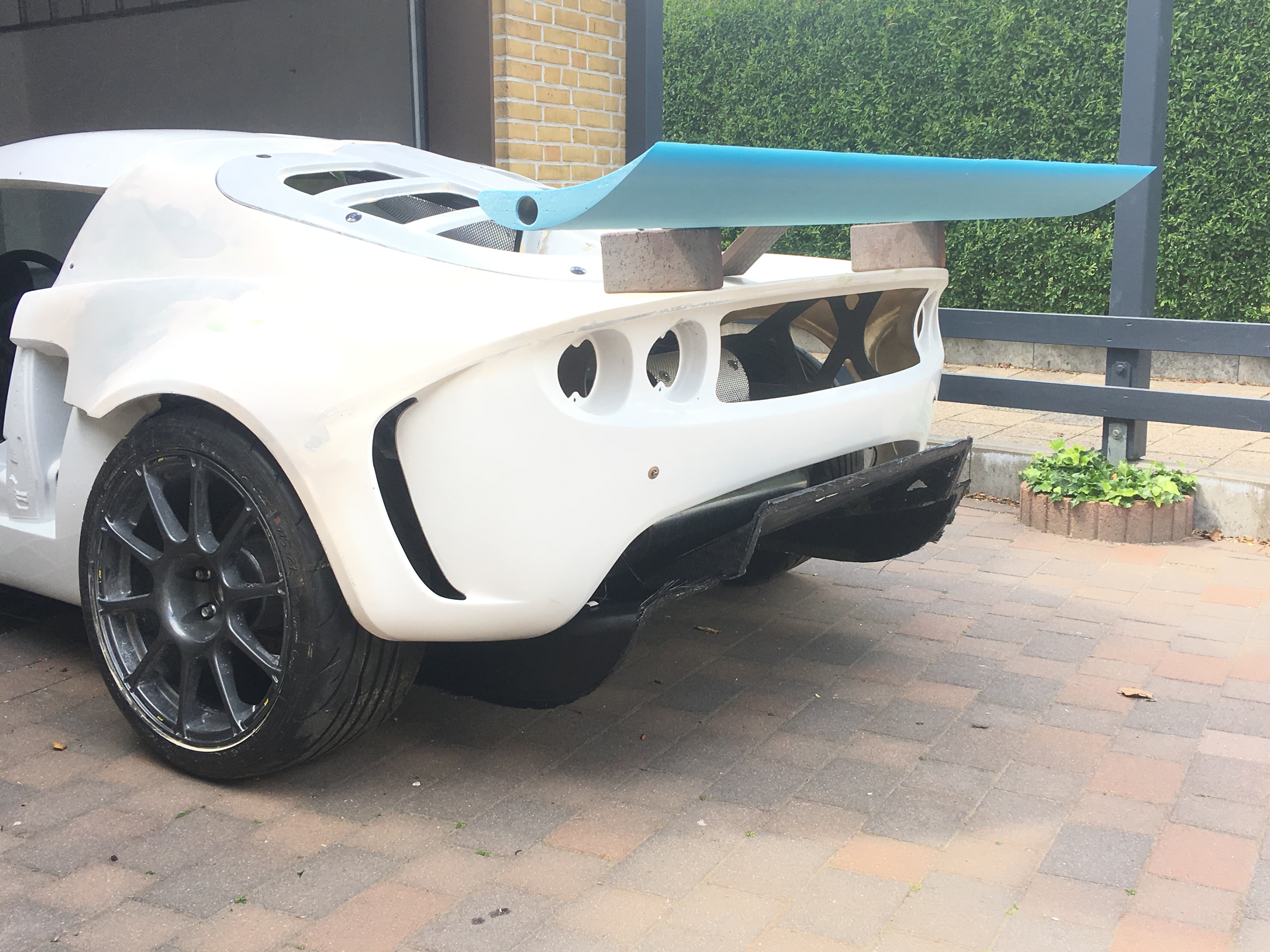
first iteration i think will be low-mounted single element. ive got a second chord for a dual element (lower plane dedicated to the diffuser) in case i get excited, but looking at how the single plane sits, and how damn big it really is, i think a single plane will be way more than enough. anyway, something like the pics below. i didnt have my vernier bricks with me, so measurements were only down in multiple of whole bricks for demonstration purposes.

so basically, low mounting the single plane will do a couple of things: it makes less downforce by not sitting up in the free airstream, but also make less drag. the sides (say 20-30% on each side) sit in pretty clear open space and should get a healthy direct airfeed. the middle will be less efficient as a wing in a pure downforce sense, but where it loses there, it gains by being in proximity to the central diffuser outlet, and will hopefully improve diffuser efficiency. so less direct downforce (and also les drag) but hopefully more diffuser action, and more downforce there with minimal drag penalty.

in either case, eyeballing it its pretty overcapitalised on rear downforce at present. so ill get it finished and running like this. meanwhile ill also work on a solid ass front splitter to try and see than i don't underspear straight off corners

IMG_6811.JPG

IMG_6814.JPG

IMG_6820.JPG

#1204 Aerodynamic

Aerodynamic

    Billy No Mates

  • PipPipPipPipPip
  • 1,455 posts

Posted 09 June 2019 - 04:08 PM

Can I say again?, very nice. And that sexy ass. Not yours but this cars.


What is the purpose of the Car? And what is your expericence of previous cars?!

I Think The natural angle of that Wing and if the diffuser works as intendent

this car will produce a whole lot of downforce. I don´t know if there is such thing as too much, but 

This should start compress the rear suspension.


What will you do for the front? I find my Aero balance to be a bit too much to the rear and will make Splitter extenders (That I can bring to track Days)

But I also run my car on the road and don´t want to much attention from the police.


I mean, Test the thing, Make upp ideas how to create more or less  downforce for front or rear if you

need to change the balance once it´s running.


Br, Per


#1205 Doctor Ed

Doctor Ed

    Need to get Out More

  • PipPipPipPip
  • 1,188 posts
  • Location:Germany

Posted 09 June 2019 - 05:29 PM

this car: nothing specific really. i don't have the time (nor money) to go run in a race series, so literally just making it as quick on paper as possible, not paying any attention to series rules or whatever, then ill just go drive it wherever theyll let me. Trackday, time attack, hillclimb etc. If it looks like it evolves in one particular event direction or the other, ill adjust its spec as required. I also anticipate getting it road registered (although I may have to tone it down a touch to make that happen). well see. first of all I'm just enjoying building it.

the front will get a bloody big splitter with a bit of underbody aero. ive bolted anchors into the chassis long ago (whilst it was still stripped minus cashbox) so there's some serious substance there to hang a big load bearing member off :)

previous cars? have built a few, but this is the most comprehensive thing I've ever tried doing

oh... and here's a vid to give the wing and diffuser a bit of 3D


#1206 FLD

FLD

    WANNABE MY LOVER

  • PipPipPipPipPipPipPipPip
  • 13,717 posts
  • Gender:Male
  • Location:Near nantwich
  • Interests:Tugging my todger.

Posted 10 June 2019 - 08:54 AM

I like that wing!  Have you considered making a curved one to match the rear profile of the car?  It's a ball ache on the profile as it changes with the curve due to the direction of airflow no longer being tangential but it looks loads better to my eye.  Perhaps one for a CAD program to cut your core.  I assume you're going to vac form over the core like a glider wing?


#1207 Doctor Ed

Doctor Ed

    Need to get Out More

  • PipPipPipPip
  • 1,188 posts
  • Location:Germany

Posted 10 June 2019 - 12:22 PM

It's a ball ache 


and that pretty much sums up why its a straight chord :)


and yeah, vac bagging carbon over the core 


Edited by Doctor Ed, 10 June 2019 - 12:29 PM.


#1208 FLD

FLD

    WANNABE MY LOVER

  • PipPipPipPipPipPipPipPip
  • 13,717 posts
  • Gender:Male
  • Location:Near nantwich
  • Interests:Tugging my todger.

Posted 10 June 2019 - 01:33 PM


It's a ball ache 


and that pretty much sums up why its a straight chord :)


:lol:


#1209 Doctor Ed

Doctor Ed

    Need to get Out More

  • PipPipPipPip
  • 1,188 posts
  • Location:Germany

Posted 19 June 2019 - 07:24 PM

Scrubbed up ok :)

Ridiculous amount of work altogether tho. Note to self: don’t ever break this.

IMG_7194.JPG

IMG_7195.JPG

#1210 Doctor Ed

Doctor Ed

    Need to get Out More

  • PipPipPipPip
  • 1,188 posts
  • Location:Germany

Posted 05 July 2019 - 11:08 AM

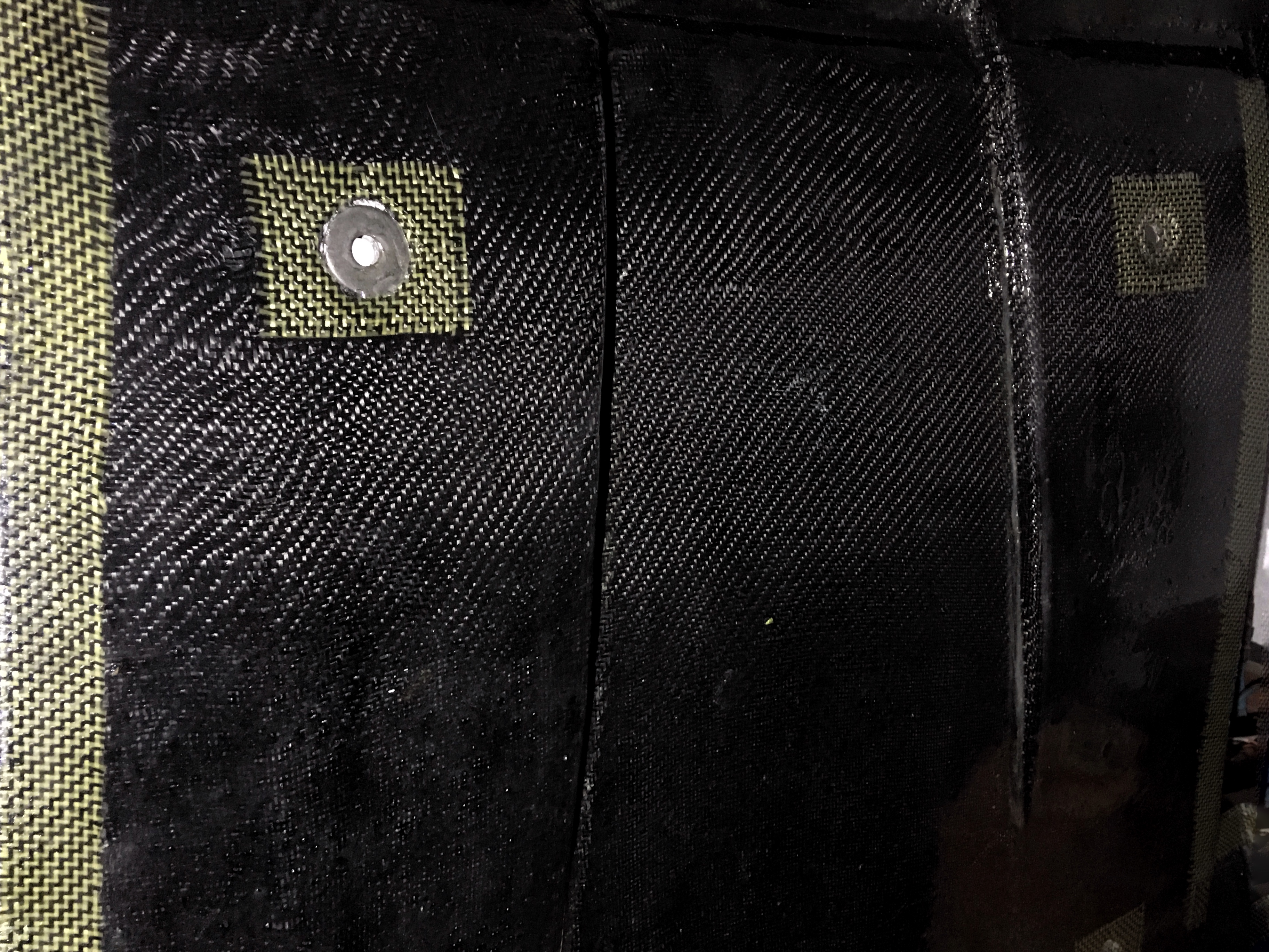
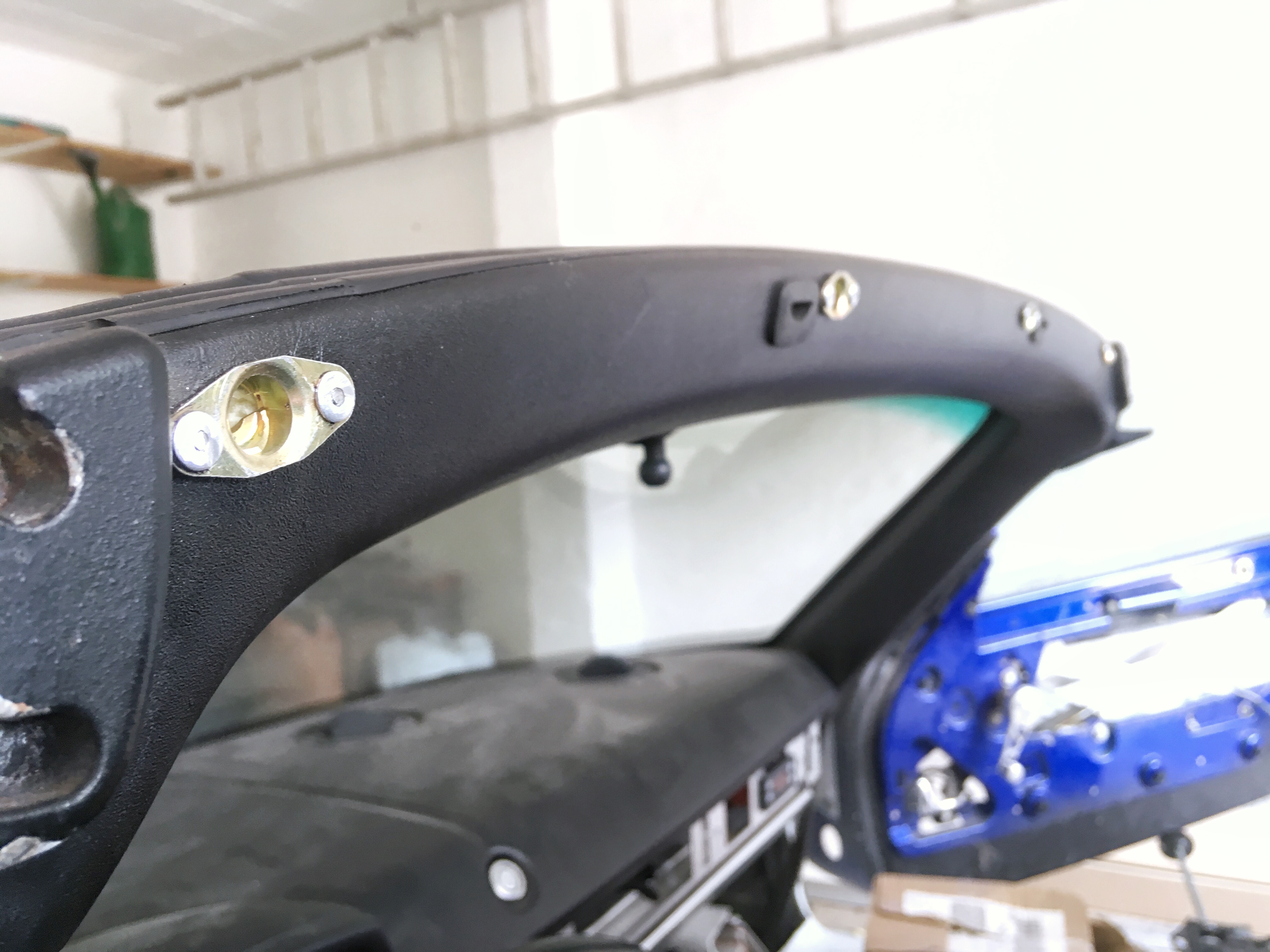
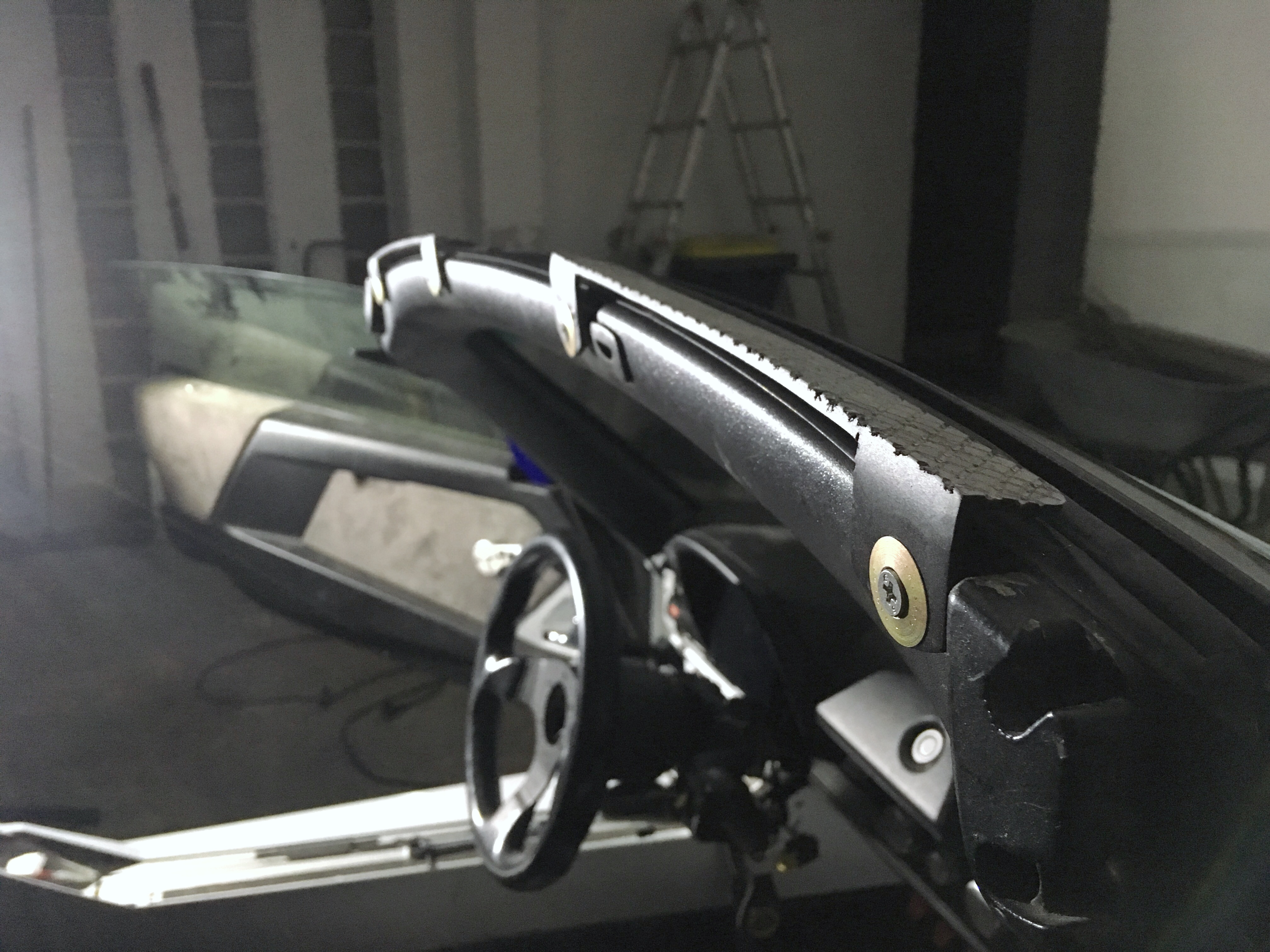
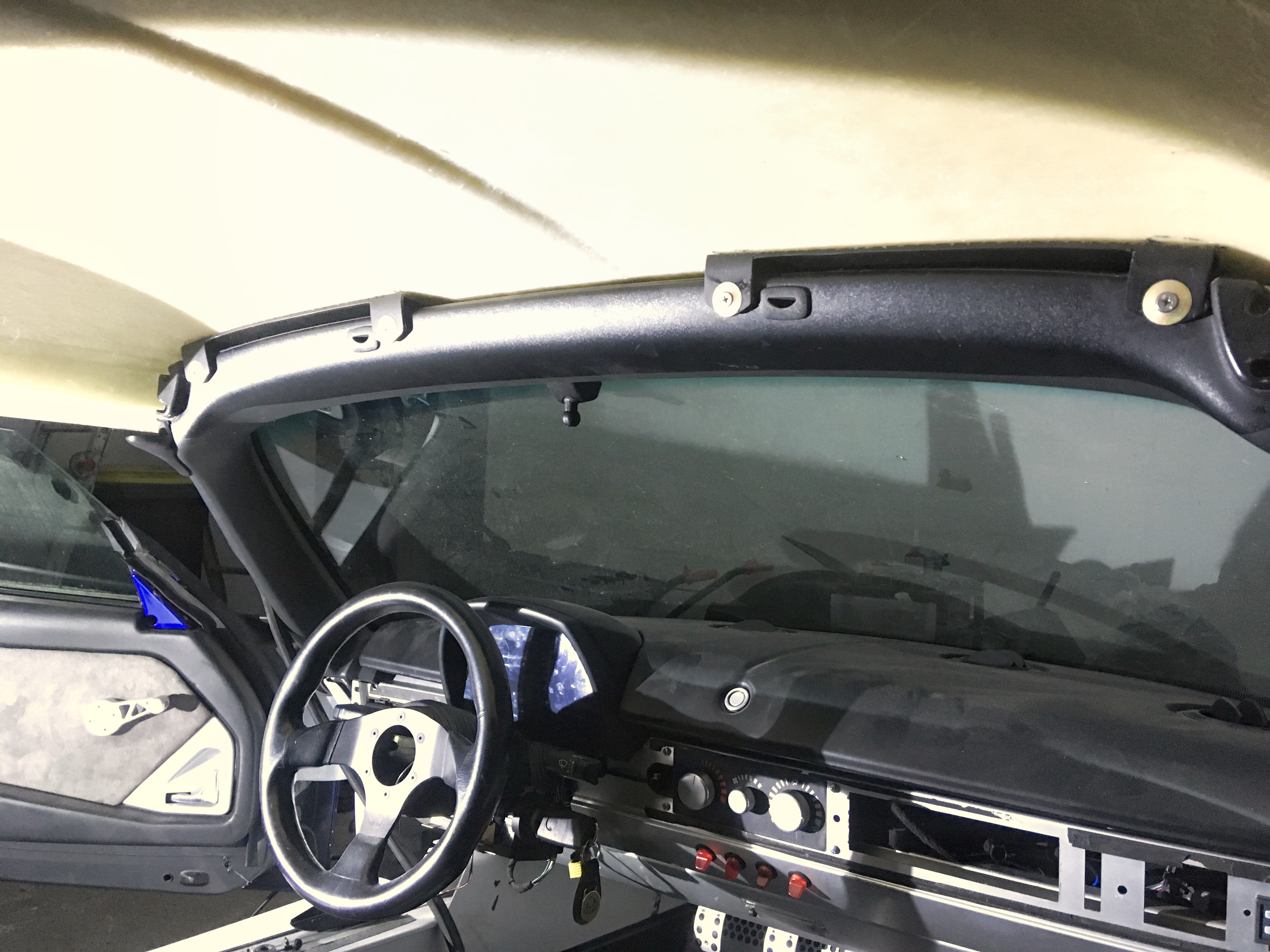
And in a low budget project binky spin-off... I’ve spent 2 days making brackets for the single skin roof. First effort got binned after eyeball-o-meter disagreed with maths, and now going with version 2: camloc quick release roof. yes i had to recess the camloc anchors into the windscreen frame. the camlocs work in sheer, and have some spring-loaded axial flexibility, so won't be too demanding on the windscreen frame. the brackets will be bonded with sika 255 to the roof, and ill throw in some flush flanged rivets to create a mechanical lock stabilising the urethane, but it'll still be a flexible joint allowing a bit a twist and vibration without the thing ripping apart

 
IMG_7571.JPG
 
IMG_7573.JPG
 
IMG_7572.JPG


#1211 Aerodynamic

Aerodynamic

    Billy No Mates

  • PipPipPipPipPip
  • 1,455 posts

Posted 05 July 2019 - 05:33 PM

I like this, simple budget working solutions.


good work.


And in a low budget project binky spin-off... I’ve spent 2 days making brackets for the single skin roof. First effort got binned after eyeball-o-meter disagreed with maths, and now going with version 2: camloc quick release roof. yes i had to recess the camloc anchors into the windscreen frame. the camlocs work in sheer, and have some spring-loaded axial flexibility, so won't be too demanding on the windscreen frame. the brackets will be bonded with sika 255 to the roof, and ill throw in some flush flanged rivets to create a mechanical lock stabilising the urethane, but it'll still be a flexible joint allowing a bit a twist and vibration without the thing ripping apart

 
IMG_7571.JPG
 
IMG_7573.JPG
 
IMG_7572.JPG


#1212 Doctor Ed

Doctor Ed

    Need to get Out More

  • PipPipPipPip
  • 1,188 posts
  • Location:Germany

Posted 05 July 2019 - 11:35 PM

so much effort goes into simple! i wish simple was actually simple!


#1213 Doctor Ed

Doctor Ed

    Need to get Out More

  • PipPipPipPip
  • 1,188 posts
  • Location:Germany

Posted 06 July 2019 - 11:07 PM

well another job that took longer than anticipated, lol...

not particularly versed in things lotus, i hit up some lotus forums to check out how these rear lights are supposed to work. yeah, well apparently that's not a simple question. lotus made the lights a certain way, then due to EU something something decided to rewire them and blank some bulb holders to meet some certification, but in the US they got a different wiring layout because the yanks like to indicate with their brake lights or some sh*t. LHD/RHD has issues with single sided fog lights and deleted reverse wiring etc. ugh, headache.

then, to make it more fun, lotus ppls have decided that the lights are *the* thing to modify, so there's 100's of posts and pics of modified lights with hacked wiring, diy LEDs etc

so at the end of all this ive not really got any idea how the std EU lights are supposed to be wired / light up. my lights and the bulbs and holders they have resembled nothing of the examples i found online. and even then, one light circuit looks to be half wired, but has never been connected to the main loom, and has never functioned. wtf.

so i made up my own, park, brake and turn are hooked up and working. reverse (which ill make function on both sides) needs to be modified in the harness sub loom. and the foglight... thats only supposed to work on the left (drivers) side, im currently using that bulb as part of the complete brake display. i need to make a mini sub loom with a 2 relays so i can illuminate that bulb from both a brake input, and the foglight input (without them crossing over)

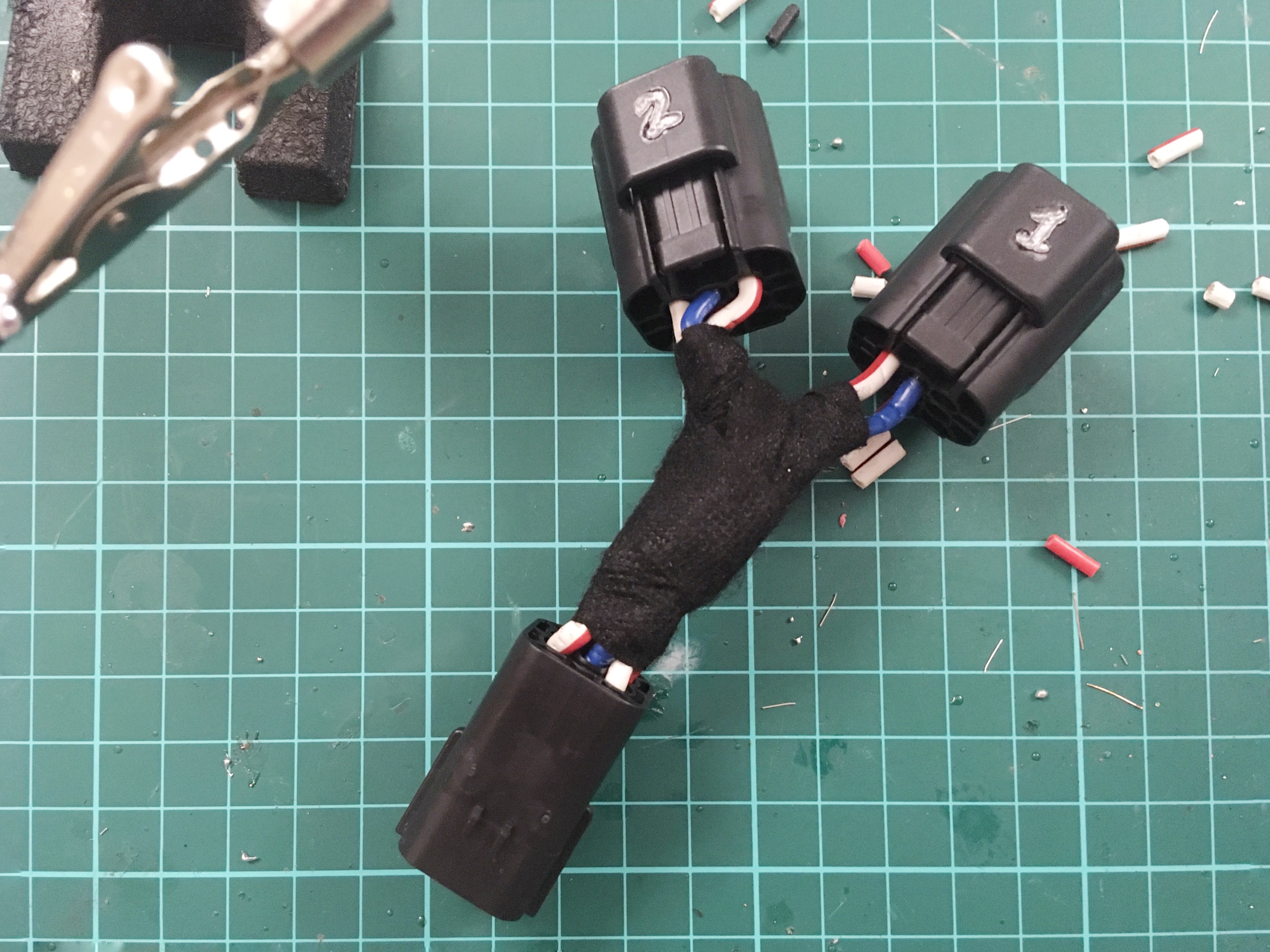
so, adapter loom from the single VX to the twin Lotus lamps

IMG_7605.JPG

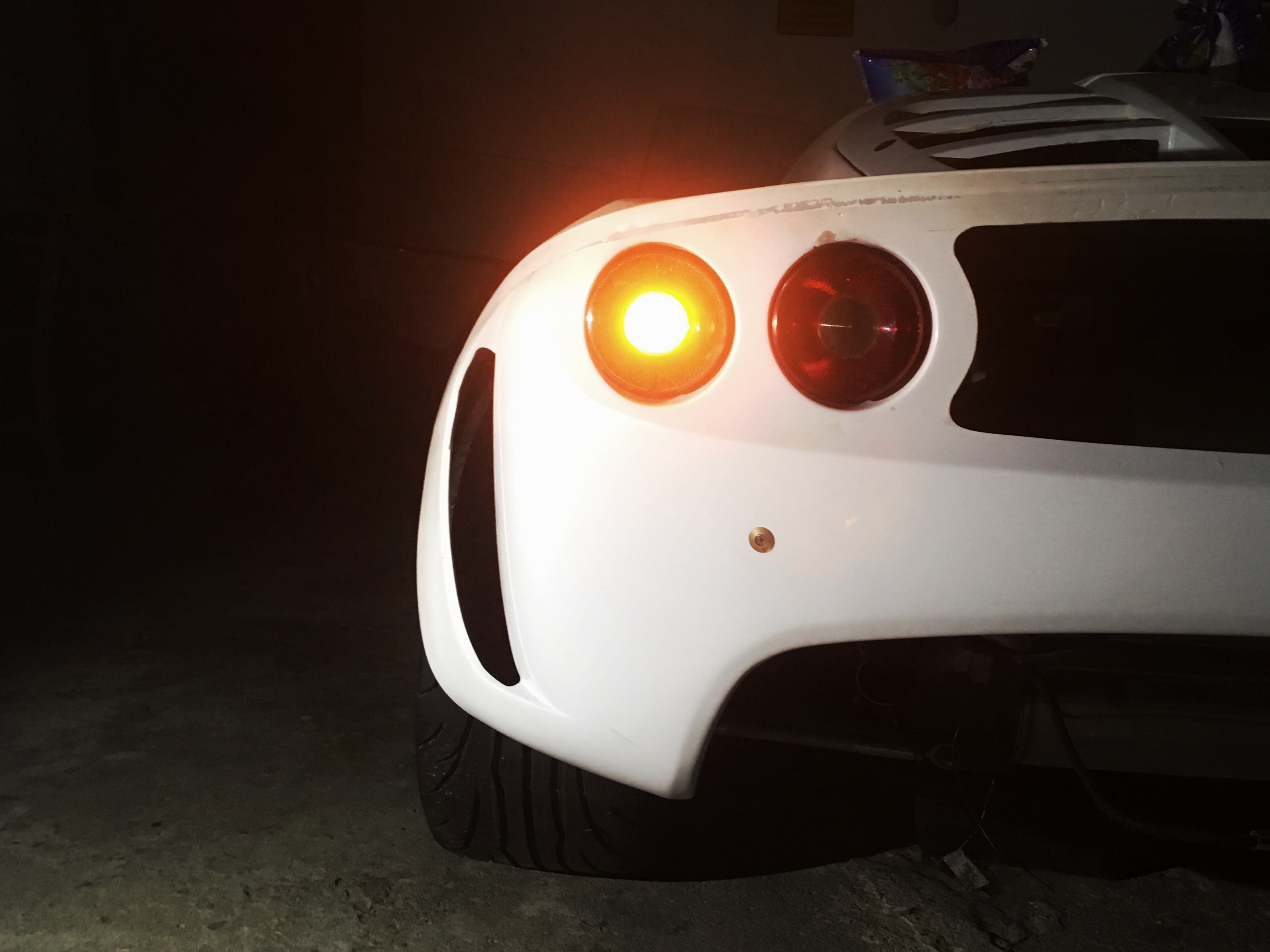
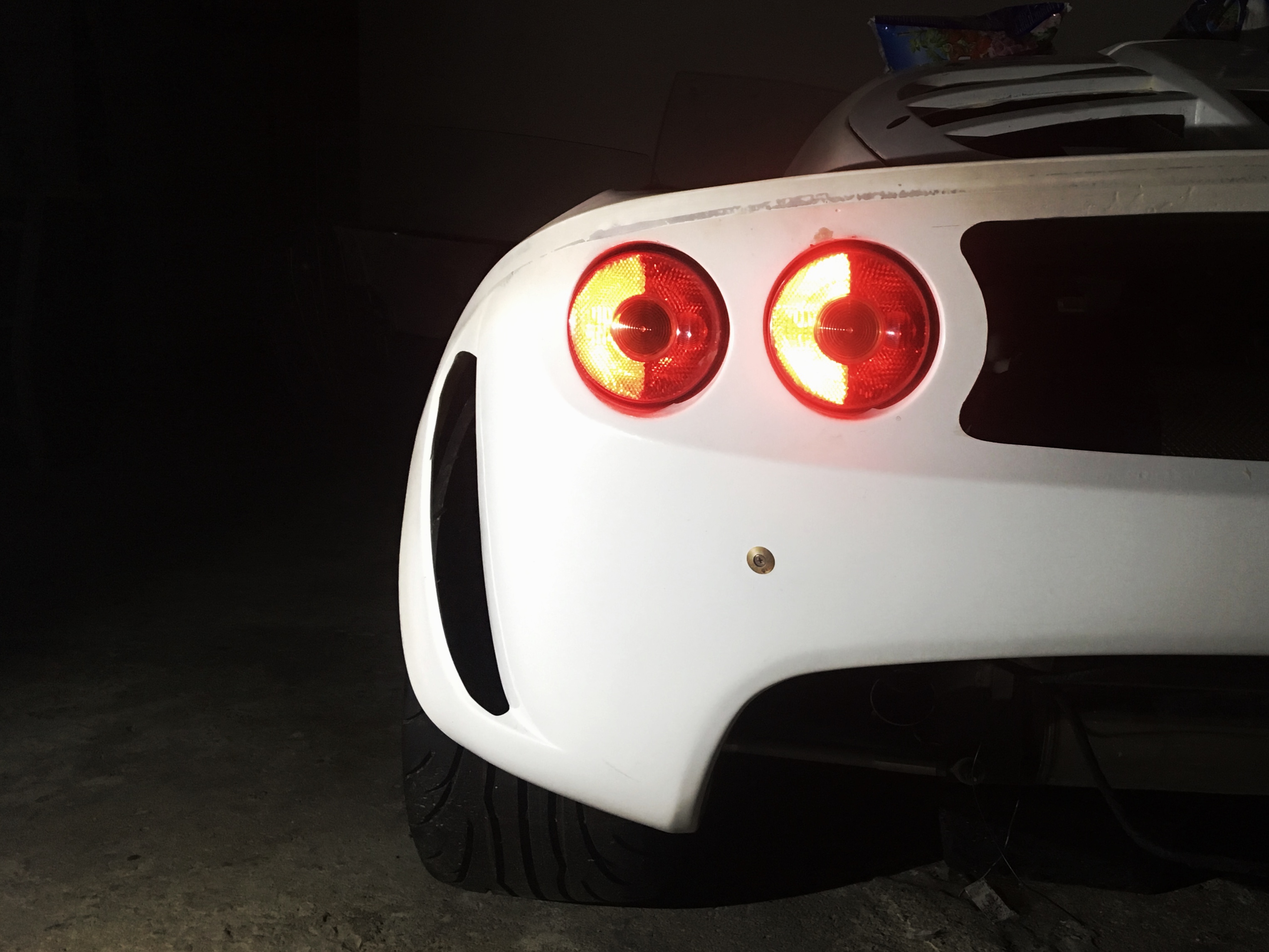
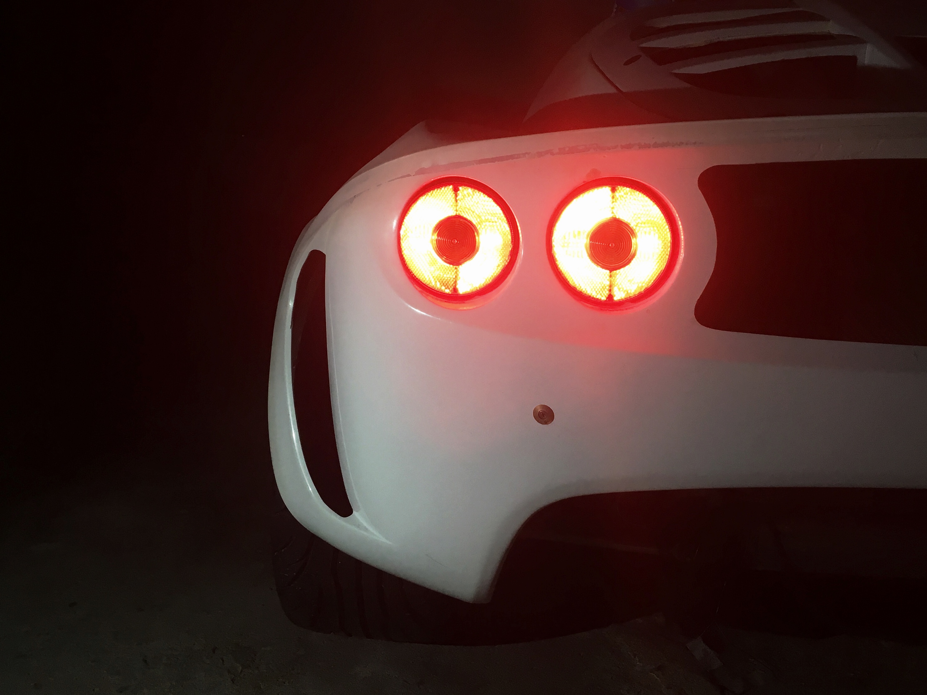
and the light sequence ive currently got working (no idea if this is normal, or what?)

turn
IMG_7608.JPG

park
IMG_7607.JPG

brake
IMG_7609.JPG

#1214 Arno

Arno

    Need to get Out More

  • PipPipPipPip
  • 1,237 posts
  • Gender:Male
  • Location:Netherlands

Posted 08 July 2019 - 08:18 AM

Not standard  :)


The incandescent rear lights on the S2 were set up from the factory very simply:


OUTER units:

- Indicator (center), yellow/amber filter

- Both ring segments regular lights

- Outward half-ring segment also brake (P21/5W bulb)


INNER units:

- Reversing lights (center), clear filter

- No lights on regular lights

- Inward half-ring segment for rear foglights


So basically the OEM setup only uses the outer units for all regular light uses and the brake lights.


The inner units are only used for reverse and rear foglights.


The back-story from Lotus at the time was that the original design was supposed to light all 4 rear lights for normal rear lights, but this ran afoul of type approval regulations at the time as the distance between the light units meant that the 'dead space' between them when added to the total surface area dropped the light output per cm2 below the threshold.


So by removing the inner units from the normal light function the imagrinary 'box' drawn around the remaining rear light unit has much less dead space and it passed.


As a result, very early/demo/pre-production S2 units were 'open' on the back for all 4 light bulb holders and just had 2 holders with the wires cut as 'plugs' in them. 


Also the very early/demo/pre-prod ones with this setup used P21/4W bulbs and different wiring compared to the later production cars with 'closed off' units and that use P21/5W bulbs. The reason for the 4W on one section of the inners is that the foglight half-ring sections are painted inside with a much more 'mirror like' finish and a 5W shines brighter in them. The regular light reflectors all have a more grey-ish reflector surface.


(and yes.. it's just silver and chrome paint inside on the reflectors ;) )


So it's common to 'mod' these by dremeling the opening back in the closed off (inner) units and getting your paws on some pigtails and bulb holders and get the orignal S2 design working.


Still doesn't change anything as far as brake/indicator/reverse/fog goes. It just lights up all full 'rings' for the normal rear lights too.


Your setup works fine too. Do whatever you like/want  :D


Bye, Arno.


#1215 Doctor Ed

Doctor Ed

    Need to get Out More

  • PipPipPipPip
  • 1,188 posts
  • Location:Germany

Posted 09 July 2019 - 08:19 AM

someone knows what they're talking about! nice, thanks Arno :)

have to say im still a touch confused when it comes to my specific lights though.

each lamp has 2 factory "open" sockets which haven't been dremelled. they're mirror finish internally, and each has one 21/5W and one 21W bulb (as indicated by the oem labelling on the light bodies).

from those bulbs, the tails to the outer 21W

#1216 Doctor Ed

Doctor Ed

    Need to get Out More

  • PipPipPipPip
  • 1,188 posts
  • Location:Germany

Posted 09 July 2019 - 09:33 AM

... tails to the outer 21W look originally cut, the plugs are blanked, and the rest of the loom doesnt look manipulated. maybe american lights? its confusing as hell in any case!

i like how I've rigged them up, and the full array of 21W/21W 21W/21W on brakes is pretty intimidating!

#1217 Arno

Arno

    Need to get Out More

  • PipPipPipPip
  • 1,237 posts
  • Gender:Male
  • Location:Netherlands

Posted 09 July 2019 - 11:44 AM

Depends where you got them.. The federal elise ones were modified to comply with the USA regulations as you already mentioned because they 'blink' the red lights and normally don't have the amber/yellow indicator fitted so all bets are off on those B)


For EU/UK vehicles there's basically 2 types of standard light units fitted to a car:


- with yellow center (internal) lense -> outer units (indicator)

- with white center (internal) lense -> inner units (reverse light)


The inner ones should normally have 1 blanked off socket (unless dremeled open or very early lights) and the open section should have a highly 'silvered' reflector as this is the foglight. (BTW.. Very early unit P21/4W sockets on these are white)


The outer ones should have both main bulb connections open, but the relfector is more of a greyish/matte coating.


No clue what they did on the Federal units and wether or not they got different (eg. more mirror-like) reflectors on all units.


BTW.. They are not too hard to take apart. If you first cut the glue line between the alu base and the acrylic cover and scrape that out, then heat them in an over to abour 125c for a few minutes you can usually slide a thin blade between the acrylic cover and the alu base to cut the glue and separate the pieces. You'll find that the center reflector for the reverse/indicator bulbs is just a loose alu section sandwiched inside (this normally rattles on most cars :P )


The acrylic cover also is multi-part in itself. A loose separate inner lense for the indicator or reversing light and a clear/uncoloured inner light-scattering layer. The latter seems captured permanentely as it looks like this, together with the outer center and 'ring' section was either superglued or friction/ultrasonic plastic welded together into 1 piece at the point where they meet.


Sometimes the alu housings can corrode badly and creep up in the reflectors if they get moisture in them.


When using all lights as brakelights you may want to keep an eye on the brake light switch and wiring as you'll be pulling 84W instead of 42W as normal. Light up all 4 rings and you'd go to a cool (hot? ;) ) 168W


Bye, Arno.


#1218 Rosssco

Rosssco

    Scary Internerd

  • 4,181 posts
  • Gender:Male
  • Location:Aberdeen

Posted 09 July 2019 - 12:06 PM

Some information on this website (and pics).


https://www.gregsrac...-exige-esprit-1


#1219 Doctor Ed

Doctor Ed

    Need to get Out More

  • PipPipPipPip
  • 1,188 posts
  • Location:Germany

Posted 11 July 2019 - 11:43 AM


When using all lights as brakelights you may want to keep an eye on the brake light switch and wiring as you'll be pulling 84W instead of 42W as normal. Light up all 4 rings and you'd go to a cool (hot? ;) ) 168W


given that the brakes dont stay on typically very long, hopefully things can cope with an intermittent 15A

might look at some LEDs though (if they even work with that 6V backround voltage) and drop the watts


PS, mine are defintely not dremmeled open, the interiors are all mirror shiny, the turn and reverse sections are functional, and the main rings of all lights are each populated (from factory) with 21/5W and 21W on each side of the lens. lol


Edited by Doctor Ed, 11 July 2019 - 11:46 AM.


#1220 Doctor Ed

Doctor Ed

    Need to get Out More

  • PipPipPipPip
  • 1,188 posts
  • Location:Germany

Posted 18 July 2019 - 08:55 AM

round peg in a square hole time...

need to try and blend the curvy rear quarters and air intake with the square door and body of the vx. the swoop of the door line and the curve into the air intake is one of the defining features of the exige shape and flow. can't really afford to fcuk this up, as it'll look like ass if its not right

IMG_7897.JPG

IMG_7898.JPG

IMG_7900.JPG

IMG_7901.JPG


4 user(s) are reading this topic

0 members, 3 guests, 0 anonymous users


    Bing (1)