I'm wondering if anyone has a picture of how the bottom boost pipe from turbo routes to get to the intercooler, my Saab build (some of you might have seen on Facebook) needs to be all custom boost hoses, but I couldn't work out how it gets into the areas where the charge cooler goes, does look very tight and also is the pipe 2" in diameter? Any pics or advice would be appreciated
Thanks
Phil

Intercooler Route
Started by
export001
, Jun 02 2016 07:51 AM
18 replies to this topic
#1

export001
-
-

- 116 posts
Member
- Gender:Male
- Location:Leeds
- Interests:If you call constantly breaking the vx then yes
Posted 02 June 2016 - 07:51 AM
#2
siztenboots
-

-

- 26,614 posts
RaceMode
- Gender:Not Telling
- Location:Surrey
- Interests:french maids
Posted 02 June 2016 - 08:14 AM
#3
siztenboots
-
-
- 26,614 posts
RaceMode
- Gender:Not Telling
- Location:Surrey
- Interests:french maids
Posted 02 June 2016 - 08:15 AM
you would really need to shroud the airflow and make a ram air scoop, plenty of foam to seal around the gaps would greatly improve the IC
#4
siztenboots
-
-
- 26,614 posts
RaceMode
- Gender:Not Telling
- Location:Surrey
- Interests:french maids
#5
export001
-
-
- 116 posts
Member
- Gender:Male
- Location:Leeds
- Interests:If you call constantly breaking the vx then yes
Posted 02 June 2016 - 08:18 AM
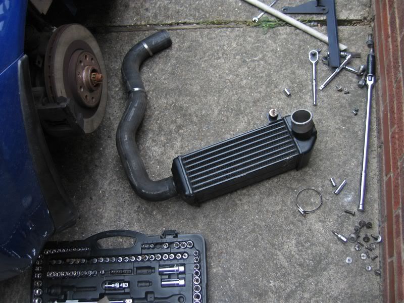
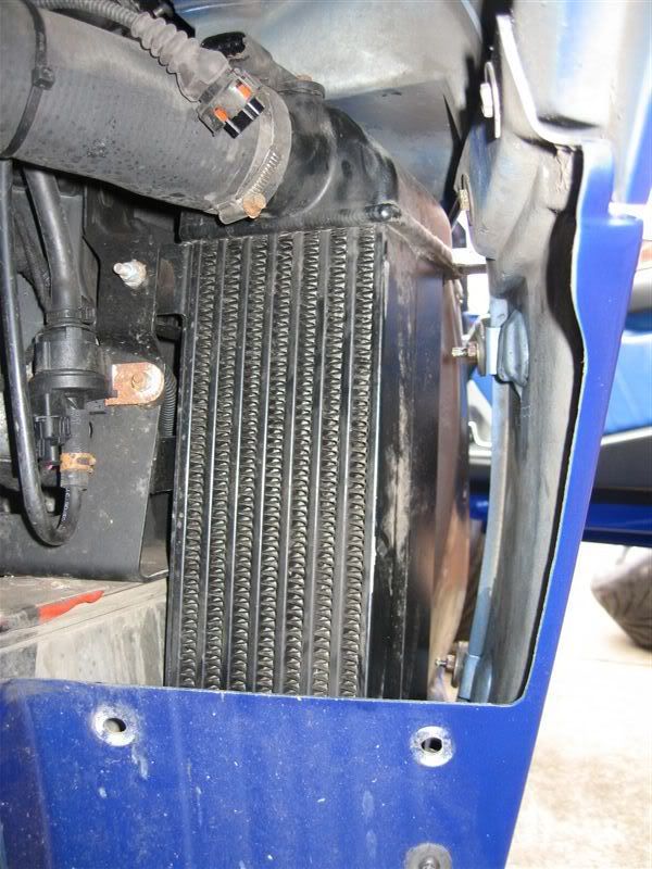
That is perfect, thank you very much for that pic, that hose there says to me that it routes over the lower arm mount then down under the chassis then the 90 is directly up into the cooler, I have a charge cooler (barrel type) to fit
#6
siztenboots
-
-
- 26,614 posts
RaceMode
- Gender:Not Telling
- Location:Surrey
- Interests:french maids
Posted 02 June 2016 - 08:21 AM
old pipe is still used for the pro alloy CC , so most likely will be okay for PWR or similar
#7
export001
-
-
- 116 posts
Member
- Gender:Male
- Location:Leeds
- Interests:If you call constantly breaking the vx then yes
Posted 02 June 2016 - 08:23 AM
Mine was originally a NA and I have no boost hose at all, it's a custom build now it's the 1st Saab B204 vx220 👍🏼 in using a similar to pwr cooler apart from its got huge 3" inlet and outlets which will have to have reducers on, is the standard boost pipe 2" can you tell me please?
#8
siztenboots
-
-
- 26,614 posts
RaceMode
- Gender:Not Telling
- Location:Surrey
- Interests:french maids
Posted 02 June 2016 - 09:14 AM
from memory its all 63mm
#9
export001
-
-
- 116 posts
Member
- Gender:Male
- Location:Leeds
- Interests:If you call constantly breaking the vx then yes
Posted 02 June 2016 - 09:19 AM
That's 2.5" ain't it
#10
siztenboots
-
-
- 26,614 posts
RaceMode
- Gender:Not Telling
- Location:Surrey
- Interests:french maids
Posted 02 June 2016 - 09:23 AM
Yep 2.5", what size throttle body are you running, I know the B204 is quite a tall engine, but the intake manifold is good. Seen these run almost stock at over 600bhp.
#11
export001
-
-
- 116 posts
Member
- Gender:Male
- Location:Leeds
- Interests:If you call constantly breaking the vx then yes
Posted 02 June 2016 - 09:32 AM
Standard throttle body which is 3" but reduces to 2.25" I don't suppose you got one of them bottom hoses spare have you or know of one for sale? I could use it for a template then
#12
Nev
-

-
- 11,587 posts
Nipper's Minion
- Gender:Male
- Location:Bristol
- Interests:Rock climbing, skiing, kayaking, surfing, mountaineering, budgies, chess, practical mechanics.
Posted 02 June 2016 - 10:10 AM
Hi Phil,
The B204 is a great engine to pick, one of the most robust and cheap 2nd hand engines ever in existence, way better than the Z20 or Z22. It has tons of meat around the bores, semi closed deck, strong rods and pistons. But I suspect you already know all this 
Here is something for the people who installed B207s in their cars to make them re-think their decision: http://www.serioussa...2x4tribute.html
FYI, the OEM boost pipes are two different diameters:
1. Rubber pipe from turbo to IC inlet is 2 inches.
2. Rubber pipe from IC outlet to top hat is 2.25 inches.
You are correct in your guess of how the turbo to IC OEM pipe is routed (in your #1st post).
HTH.
Nev.
Edited by Nev, 02 June 2016 - 10:23 AM.
#13
export001
-
-
- 116 posts
Member
- Gender:Male
- Location:Leeds
- Interests:If you call constantly breaking the vx then yes
Posted 02 June 2016 - 10:23 AM
Hi Nev
Thanks for the reply I don't suppose you made yours up from silicon bends did you? To suit your gt30?
Thanks
Phil
#14
Nev
-
-
- 11,587 posts
Nipper's Minion
- Gender:Male
- Location:Bristol
- Interests:Rock climbing, skiing, kayaking, surfing, mountaineering, budgies, chess, practical mechanics.
Posted 02 June 2016 - 10:24 AM
Standard throttle body which is 3" but reduces to 2.25" I don't suppose you got one of them bottom hoses spare have you or know of one for sale? I could use it for a template then
They come up on eBay from time to time, or find a breaker whos got a crashed VX. They should be very cheap as they are rarely ever needed as a second hand part. I was lucky and got given one recently by a kind gent on here, as mine had burst due to boost abuse (25 PSI)!
Edited by Nev, 02 June 2016 - 10:25 AM.
#15
Nev
-
-
- 11,587 posts
Nipper's Minion
- Gender:Male
- Location:Bristol
- Interests:Rock climbing, skiing, kayaking, surfing, mountaineering, budgies, chess, practical mechanics.
Posted 02 June 2016 - 10:27 AM
Hi Nev Thanks for the reply I don't suppose you made yours up from silicon bends did you? To suit your gt30? Thanks Phil
I did this initially for the IC to TB pipe, however I would not recommend concatenating multiple silicon pipes and joiners as this is likely to result in boost leaks in my experience. In the end I got a local welder to come round and build me a hard pipe in my garage to fit, with short silicone joiners on the ends to allow flex for engine movement. It only cost me £70 and was well worth it.
You can see my pipe run in this video (3" dia), it was a really leaky bastard that I had to double up the jubilee clips on as it moved about with the engine rocking!
Edited by Nev, 02 June 2016 - 10:37 AM.
#16
export001
-
-
- 116 posts
Member
- Gender:Male
- Location:Leeds
- Interests:If you call constantly breaking the vx then yes
Posted 02 June 2016 - 10:28 AM
You still run the standard pipe then nev? Maybe be worth me doing the same but I'm not sure my turbo location is still the same as the z20 one, as my custom manifold has moved my turbo up and towards the gearbox
#17
Nev
-
-
- 11,587 posts
Nipper's Minion
- Gender:Male
- Location:Bristol
- Interests:Rock climbing, skiing, kayaking, surfing, mountaineering, budgies, chess, practical mechanics.
Posted 02 June 2016 - 10:34 AM
You still run the standard pipe then nev? Maybe be worth me doing the same but I'm not sure my turbo location is still the same as the z20 one, as my custom manifold has moved my turbo up and towards the gearbox
Yes, for the Turbo to IC I use most of the OEM pipe, but towards the end that mates with the IC I have added a section that increases its bore to 2.5" as my IC has a 2.5" inlet.
Normal boost pipe philosophy is to increase the bore steadily from turbo to engine. In particular your IC sounds good to have 3" inlet/outlet as this helps fan the air out as it fires at the matrix (rather than squirting a narrow jet at the matrix). This helps reduce pressure loss over the matrix as it promotes the charge to spread more evenly over the matrix.
Edited by Nev, 02 June 2016 - 10:34 AM.
#18
export001
-
-
- 116 posts
Member
- Gender:Male
- Location:Leeds
- Interests:If you call constantly breaking the vx then yes
Posted 02 June 2016 - 10:37 AM
That is great help nev thank you very much for that info, I shall look for a standard boost pipe and adapt it where I have to with my turbo location, the the 3" inlet and outlet is huge, the cooler itself is 5" in diameter and 10" long I'm hoping it does the job and cools well
#19
Nev
-
-
- 11,587 posts
Nipper's Minion
- Gender:Male
- Location:Bristol
- Interests:Rock climbing, skiing, kayaking, surfing, mountaineering, budgies, chess, practical mechanics.
Posted 09 June 2016 - 05:57 AM
Phil, have you started your own project thread yet? Might be nice, with lots of pics to show others how you are doing it.


1 user(s) are reading this topic
0 members, 1 guests, 0 anonymous users

