Is there anyone how knows if any other vauxhall models that have the same lightswitch bottons like vx220?? Need to change the lightswich panel with bottons
Edited by motorzon, 21 April 2020 - 09:22 PM.

Member

Posted 21 April 2020 - 09:20 PM
Edited by motorzon, 21 April 2020 - 09:22 PM.
Member

Posted 21 April 2020 - 11:27 PM
What's the problem? I've no idea if the buttons are shared.
On another car of mine some centre console buttons were playing up. New replacement weren't available and I found used on ebay but likely to have the same problems eventually (a common problem with that car). Took the switch pack to a mobile phone/PC repair place and they fixed it with new microswitches on the circuit board. Just saying in case can't find a replacement might be a fix out there.
Thetan level 15

Posted 21 April 2020 - 11:49 PM
Front fog, Head lights and Side lights switch share same 4 pin layout.
This one is often replaced with the vectra B aircon switch (proven to work), where the vx front facade is put on.
Rear fog has a 5 pin layout, that i have not seen a like for like replacement reported on.
The hazzard was found on the both Omega B as Vectra B iirc. (7 pin version!!!)
These switches layout are from the Vectra B and Omega B era, and they are getting rarer by the year, as they dissapear from the streets and breakers.
I think this community would welcome alternative switches to be tried, as the aircon ones supplies are drying up fast.
Also have a good look at he pin layout before buying on ebay, as there are some that look similar, but are not.
It also helps if you state your exact problem, as most of these switches can be saved with a good clean.
Edited by smiley, 22 April 2020 - 12:13 AM.
Thetan level 15
Posted 22 April 2020 - 12:26 AM
The replacement switch is the Vectra B Aircon switch, NOT the air re-circulation switch.
Vectra hazzard seems to be 4 pin only, so i think that one is coming from the Omega as we need 7 pins.
Super Member

Posted 22 April 2020 - 07:42 AM
Super Member

Posted 22 April 2020 - 09:06 AM
Super Member
Posted 22 April 2020 - 10:38 AM
Super Member
Posted 22 April 2020 - 10:59 PM
Someone say Plasti Dip?

Posted 25 April 2020 - 08:23 AM
.

Posted 02 May 2020 - 02:50 PM
Personally it would be easier to get a new panel made up with some more modern looking buttons that simply just push the old ones, then all that is needed is a splicing for the power for the LED.
Was thinking about this a while ago but didn't want to faff around too much and I'm not the sort of person that comes up with elegant solutions 

Scary Internerd

Posted 02 May 2020 - 03:30 PM
Thetan level 15
Posted 02 May 2020 - 03:38 PM
It has been done a few times yes.
But never posting the exact wiring job, making people hisitate to replicate i think.
Supercharger of Doom

Posted 02 May 2020 - 06:18 PM
Vocky (as usual) did it best, using a VW/Audi all-in-one type twist and pull type controller.
Scary Internerd
Posted 03 May 2020 - 07:49 AM
I'm sure the one I saw, with round buttons had the wiring schemeIt has been done a few times yes.
But never posting the exact wiring job, making people hisitate to replicate i think.
.
Posted 03 May 2020 - 01:19 PM
I'm sure the one I saw, with round buttons had the wiring schemeIt has been done a few times yes.
But never posting the exact wiring job, making people hisitate to replicate i think.
Yes it was done by -Dap-of-Oppo- some time ago.
It has been done a few times yes.
But never posting the exact wiring job, making people hisitate to replicate i think.
It's not a simple job, had a good chat with Graham about it over PM.
A good link to the wiring is here;
http://www.vx220.org...-switches-help/
Vocky (as usual) did it best, using a VW/Audi all-in-one type twist and pull type controller.
Would like to see this!
Graham's reponse to my PM was this, which he has sent to a couple of people before asking him how he did it.
The switches I used can be a direct swap, you'll just need to cut the existing terminal blocks off and crimp on some spade connectors in place of them to push onto the pins of the new switches. Should you need to extend the wires you can use some short lengths of colour coded 16.5a thin wall automotive wire.
This is the schematic for the Savage motorsport switches I used -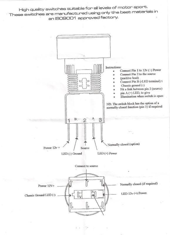
I did make a few notes of the colour combinations that can be used in relation to this which should help tell you what to put where. I am pretty sure these are all correct but it was written down from memory so please double check for yourself before going ahead. TBH it is all quite straight forward and fairly self explanatory when you have the cars terminal blocks in front of you. I left a few of the original wires unused and just tapped them off ie. the ignition switched lives for the back lighting and the conditional wires that prevent one light being on without the other as I wasn't fussed on retaining this functionality and wanted to be able to switch them all independantly.
Sidelight -
(green block, far left)
Black LED ground
Small & Large Brown/Blue wires to Pin 1
Red/Blue wire to Pin 2 + Bridge to LED positive
Headlights -
(blue block second from left)
Black - LED ground
Blue wire - Pin 2 + Bridge to LED positive
Brown/black wire - Pin 1
Front Fogs -
(brown block second from right)
Black - LED ground
Red/green wire - Pin 1
Purple/red wire - Pin 2 + Bridge to LED positive
Hazard Warning Lights -
Requires 6 pin switch with 5 push to make pins and 1 normally closed pin or the addition of a relay if using the Savage switches.
light green wire pin 1 topside normally closed with purple brown
Purple and purple brown wires to pins 2 and 3 topside pushing to make
Lower pin set (isolated from topside)
Both green whites and green red to there own pins and bridge the green red to LED positive
Black wire - LED ground
Hope that helps you out a bit, TBH even if you're not too confident in what you are connecting to what you can't go far wrong as long as you keep the wires correctly grouped, think things through and study the existing layout the worst that you should do is blow a fuse so a bit of trial and error within reason should be Ok.


Cuntpuffin

Posted 03 May 2020 - 03:47 PM
Thanks for fishing that out Giles. Details on Vocky's switch was here, I remember seeing the photos but the links seem to be broken now.
Nearly 9 years(!) later my switches are still working perfectly. The reason I have never posted the wiring details publicly is because it would have to of been done with the caveat that it was from memory and that you should seek confirmation and test for yourself, also it is specific to the Savage motorsport switches I used. I only made crude notes after having tested the wires when installing and would not like to have offered wrong information and to cause people problems.
VX wiring diagram if you need it - PDF
Thetan level 15
Posted 03 May 2020 - 04:21 PM
I understand Graham, you don't want your name on burned down vx'es.
We are at a point however that oem stuff, and replacements have dried up, making people take the risk, as it stops passing mot, making it an expensive piece of lawn furniture.
I think anybody who is into electrics a bit more then average, could save some cars.
I think it would help by understanding what leads come out of the oem blocks.

People should be grown up enough to test, and not copy whatever they find on the internet.
Member
Posted 05 May 2020 - 05:58 PM
Does it only apply to the Vectra facelift 2000 onwards or can I also use buttons from 1996 to 2000? In appearance only looks like facelift that matches.
Thetan level 15
Posted 05 May 2020 - 06:16 PM
The facade at least has the same front end from the facelift.
Not sure if anyone tried to fit a facelift facade on a pre facelift switch.
Member
Posted 08 March 2025 - 09:11 PM
I'm sure the one I saw, with round buttons had the wiring schemeIt has been done a few times yes.
But never posting the exact wiring job, making people hisitate to replicate i think.
Yes it was done by -Dap-of-Oppo- some time ago.
It has been done a few times yes.
But never posting the exact wiring job, making people hisitate to replicate i think.
It's not a simple job, had a good chat with Graham about it over PM.
A good link to the wiring is here;
http://www.vx220.org...-switches-help/
Vocky (as usual) did it best, using a VW/Audi all-in-one type twist and pull type controller.
Would like to see this!
Graham's reponse to my PM was this, which he has sent to a couple of people before asking him how he did it.
The switches I used can be a direct swap, you'll just need to cut the existing terminal blocks off and crimp on some spade connectors in place of them to push onto the pins of the new switches. Should you need to extend the wires you can use some short lengths of colour coded 16.5a thin wall automotive wire.
This is the schematic for the Savage motorsport switches I used -
I did make a few notes of the colour combinations that can be used in relation to this which should help tell you what to put where. I am pretty sure these are all correct but it was written down from memory so please double check for yourself before going ahead. TBH it is all quite straight forward and fairly self explanatory when you have the cars terminal blocks in front of you. I left a few of the original wires unused and just tapped them off ie. the ignition switched lives for the back lighting and the conditional wires that prevent one light being on without the other as I wasn't fussed on retaining this functionality and wanted to be able to switch them all independantly.
Sidelight -
(green block, far left)
Black LED ground
Small & Large Brown/Blue wires to Pin 1
Red/Blue wire to Pin 2 + Bridge to LED positive
Headlights -
(blue block second from left)
Black - LED ground
Blue wire - Pin 2 + Bridge to LED positive
Brown/black wire - Pin 1
Front Fogs -
(brown block second from right)
Black - LED ground
Red/green wire - Pin 1
Purple/red wire - Pin 2 + Bridge to LED positive
Hazard Warning Lights -
Requires 6 pin switch with 5 push to make pins and 1 normally closed pin or the addition of a relay if using the Savage switches.
light green wire pin 1 topside normally closed with purple brown
Purple and purple brown wires to pins 2 and 3 topside pushing to make
Lower pin set (isolated from topside)
Both green whites and green red to there own pins and bridge the green red to LED positive
Black wire - LED ground
Hope that helps you out a bit, TBH even if you're not too confident in what you are connecting to what you can't go far wrong as long as you keep the wires correctly grouped, think things through and study the existing layout the worst that you should do is blow a fuse so a bit of trial and error within reason should be Ok.


0 members, 1 guests, 0 anonymous users

