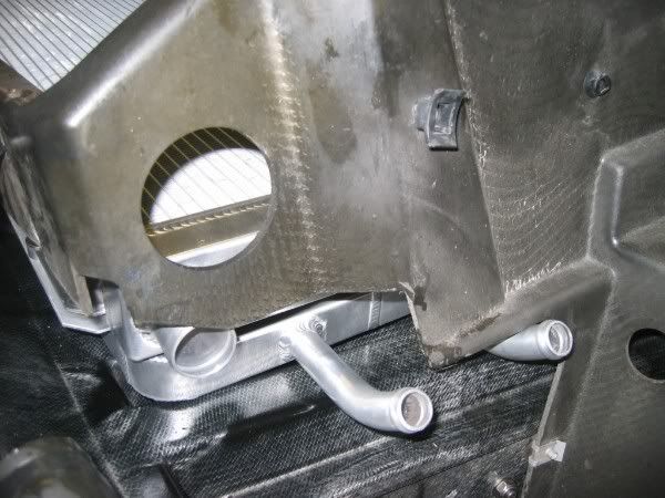
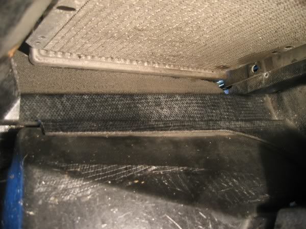
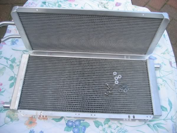
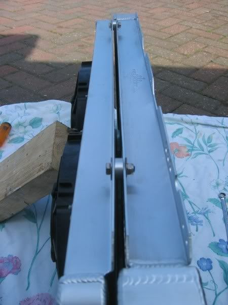
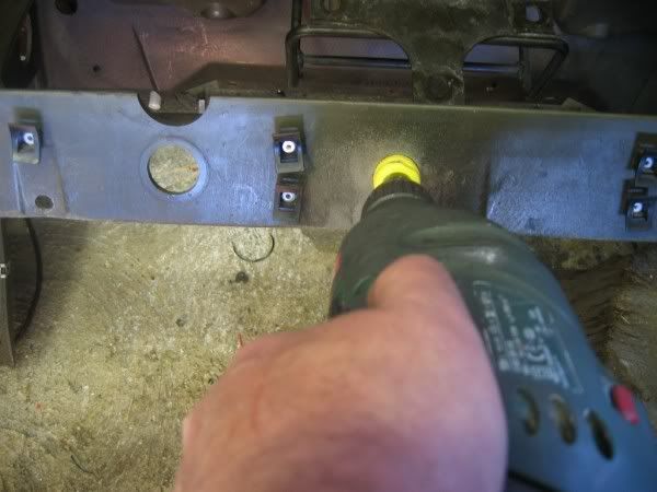
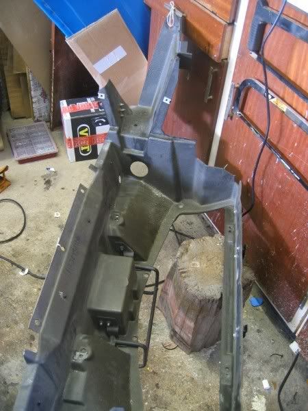
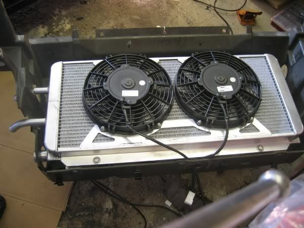
If you look into the crash box under the rads you can see that to the left (and right) at each side there is gap from front to rear.
Radiator gap
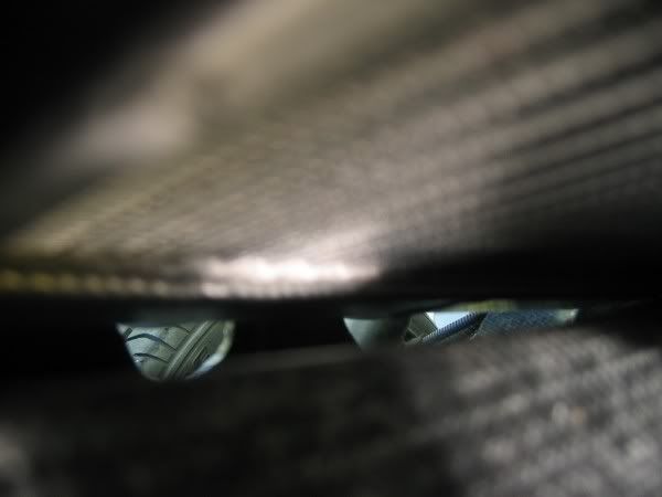
On the left is where the sponge from the original rad filled the gap between the rad plastic end cap and the crash box below. Assuming the gap was sealed for a purpose (aid/direct airflow through the rad rather than allowing it to escape from the side, I decided to fill not just one, but both sides with the removed foam. Remove housing/rads, ensuring you tighten up the four top securing bolts without disturbing the established final rad fine orientation.
Take the piece of sponge and cut it in half longitudinally.
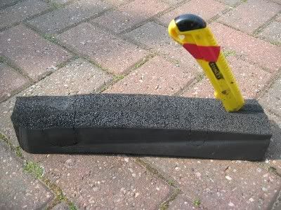
Replace the rads/housing and check that the foam will compress to allow it to seat sufficiently low to allow the rear screw holes to align with the ‘C’ clip holes.
With double sided tape secure the foam strips on either side of the pre rad ends. The outer face of the sponge is a pressure fit only.
sponge on rad end
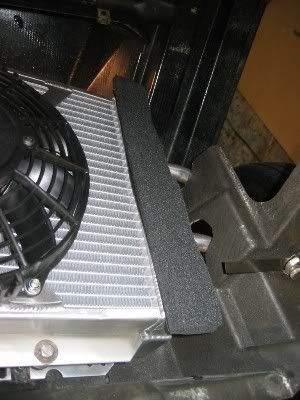
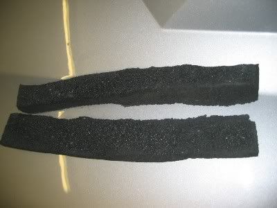
Replace the rads/housing on the car to examine the fit. I found the foam was too thick, removed the rads again and carefully sliced another 1/3 off each sponge strip. Again do not throw these strips away as they will be used later for something else.
Remaining sponge
Before you replace the rads/housing for the final time, ensure that the 3 ‘C’ clips at the rear top of the crash box are all correctly aligned in readiness for the PITA job of replacing the screws.
As these 3 screws are so difficult to remove and replace, this is how I did it, assuming they haven’t rusted beyond redemption which mine hadn’t. If you choose to attempt my way you will need one of these.
Grips
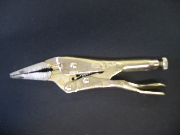
Irwin Vise-Grip long taper nose adjustable, about 8 squids form Haulfrauds. This is an invaluable tool for all sorts of situations.
Starting on the left hand side by the ABS unit there is a screw head in the rad housing surrounded by the brake pipes and difficult to reach. Above it is the loom support which is attached to the rad housing. Even if you can get a screwdriver in it’s almost impossible even with small hands to exert any real pressure to undo the screw. It’s better to use a small ratchet with the bit on an extension but even then applying pressure is difficult but can be done to some degree with a the extension shaft through a small ring spanner using the spanner to exert pressure. Using a wood chisel (I thought the loom support was all plastic) I put it between the loom support and the rad housing and whacked it with a mallet to cut it off. I then found it had a large rivet through the centre so I’d fkuced my chisel but it did the job and the chisel will re sharpen.
Place a piece of tapered wood between the brake pipes and the rad housing just sufficiently thick to (being very carefully so as not to damage) lever the brake pipes very gently and not a lot so that it’s possible to get the tips of the grips into the gap to lock on the screw head. You then have just enough room for about a ¼ turn on the screw. Once you’ve got it moving it should come out fairly easily if not heavily rusted. The other two (centre and right) are somewhat easier because they are more accessible.
This first screw is the worst, and replacing it is equally difficult. I used the ‘screw and washer dangling on a very thin piece of copper wire’ method to get it back in. By dangling in this manner you don’t have to worry about dropping the thing while you contort your fingers through the maze of brake pipes to get the screw thread to take on the C clip thread.
Fan connections
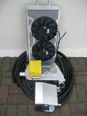
The two fan connections have blue + and black – connecting wires. Both fans can be connected in parallel (as I did) or one can be connected to the original supply and one connected to an independent switch to be operated from the cabin. Your choice.
I took the connector from the fan taken off the car and cut six inches along the wire. This is also a Spall fan with blue/black wires and I assumed they could safely be connected to the blue/black wires of the new fans.
It would have been convenient here if Pro Alloy had supplied the female block connectors and pins to match the male on the new leads.
As they didn’t I cut the block connectors off, spliced blue to blue and black to black, and joined them to the wires off the old fan.
To be 100% certain the connections were correct and the fans would blow the right way, I used an old battery, placed a sheet of paper on top of the rad, and carefully made a blue+ black- connection from the plug pins to the battery. The fans blew the paper off the rad confirming the connections were correct.
To replace the rubber grommet that holds the fan wires away from the rad housing at the new hole I had to trim the grommet somewhat to fit.
Connect radiator hoses
Use 5 year (red) coolant 50/50 with water. If you live in a hard water area buy demineralised/distilled for this. If you live in a very soft water area as I do, from the tap will do. Fill coolant expansion tank and continue as system fills. Bleed system.
CC Hoses front to rear.
Having replaced the rad and housing you are ready to cut holes in the rear of the offside front rear wheel arch to take the hoses down the sill.
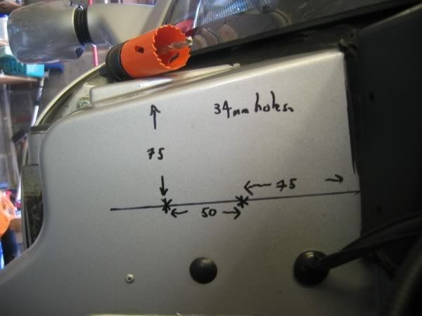
The kit instructions (with picture) specify 34mm holes. I couldn’t find a 34mm cutter so I bought a 35mm instead figuring that 1mm wouldn’t make much difference, and this was so.
The centre vertical centre line of the first (right hand) hole is 75 mm from the bulkhead edge. The centre vertical line of the second hole is 50mm from the first vertical, or, 125mm from the bulkhead. You need to establish these lines first because the centre line depth of both holes is determined as being 75mm from the top of the sloping bulkhead down the second hole vertical line. That is you have to calculate distances ‘out’ from the bulkhead and the distance ‘down’ from the sloping upper top corner. Sounds complicated but it’s easy when you see the pic.
Holecuts mark up
Cutting
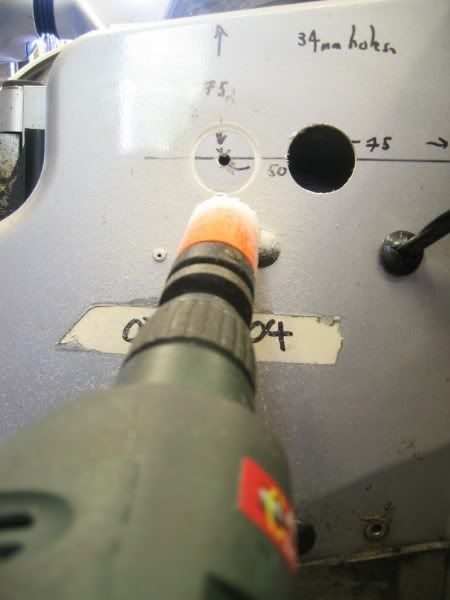
When the holes are cut, grease the edges with silicon grease and insert the two 28mm (ID) by 9mm by 43 mm rubber grommets into the holes and make sure the groove seats properly on the bodywork. The grease helps this.
Side Sill
The side sill has two supports inside at right angle to the cavity and completely blocking them, made of high density foam. Before you can run the hoses down the sill you therefore need to clear the way first.
To do this I used an old piece of plastic wiring conduit. I sharpened one end and at the other made two holes at right angles to each other about an inch from the end. I enlarged the holes with two 3†screws screwed in half way, and then removed. I ran the conduit/whatever in through the outer hose hole and down into the sill.
If you place a small torch on the sill inner floor facing aft you can use the mirror on a bendy thing to look down the length of the sill and make sure the conduit is not fouling the brake pipe or the rad supply pipe, both of which are in there. Also I have the traction control wires running in there so I had to ensure I didn’t snag/damage them in the process.
Using mirror to look down inside sill with torch laid on sill floor.
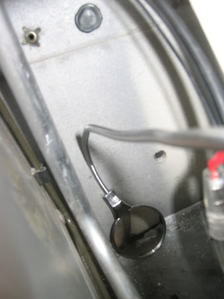
I pushed the conduit/whatever through under the foam until it come out by the rear wheel arch and carried on feeding it through until the end prepared with screw holes had passed down into to the base of the sill. In the picture below top left you can see the conduit passing between the outer sill wall and the foam.
Inside Sill 1
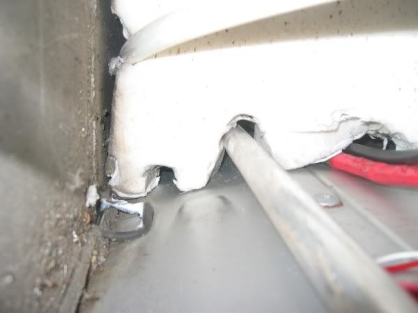
Reaching in I pulled the conduit up bending it so that it came out of the cubby hole aperture. I then screwed the two screws in at right angles to each other, forming a cross, pushed that back down in to the sill aperture, and from the rear of the car pulled the conduit all the way through and out.
Conduit out of cubby hole access
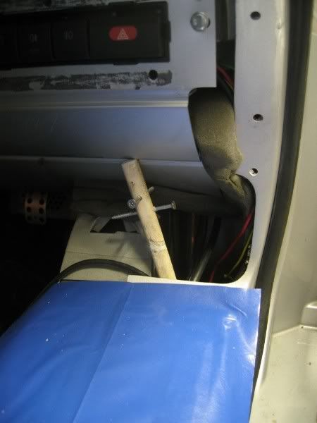
I had to do this three times to fully clear the sill. Below half done, you can see past one foam to the next,
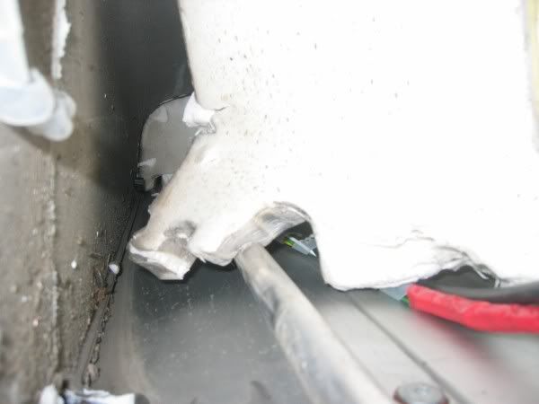
Nearly clear
This is what you have to clear to get the hoses through.
Sill foam
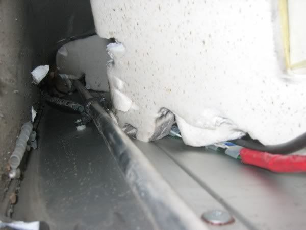
I thought it was polystyrene and would break easily but in fact it’s quite tough and dense and will not break easily so has to be pushed to one side.
Electrics
If like me you’re going to run a cable supply from the battery now is the time to do it. I measured an approximate length from battery to water expansion tank, covered it with spiral wrap for protection of the length through the sill, taping each end of the spiral wrap in place. I shrink wrapped the end leading to the battery and at the rear the length from the sill up the wheel arch to nearly as far as where the pump sill be situated bearing in mind the wires part company with one to the relay (+) and one to the pump terminals (-). In the front wheel arch bulkhead that the hoses pass through there is just below them a rubber blanking grommet in a pre cut hole. I threaded the cable through this, inserted my trusty conduit from the rear wheel arch up the sill, and bending it out of the cubby hole aperture once more taped the wires to it and drew them down and through to the rear.
The switching supply for the relay is taken from the fuelling circuit. The reason for this is that this circuit remains live for 45 seconds after the ignition has been switched off. I’m not 100% but I think this is to keep the fuel pump running so that if the engine is very hot it prevents vapourization in the system. It’s convenient because the CC pump/system continues to run/circulate for that length of time after engine switch off.
The relay supply is taken off the blue connection block that’s fixed on to and behind the coolant expansion tank bracket.
Identifying the red/grey wire in the blue block connector. Here the red wire can be clearly seen.
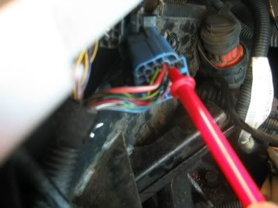
There are two blocks, the top is black and the blue one you’re looking for is below it. It’s difficult to access and I ended up removing the coolant header tank and bracket to get at it. You need to make this connection before the CC header tank goes in because after that it cannot be accessed.
The lead you are looking for is on the top (top being where the push release catch is) left hand side of the wires entering the block from the rear of the car. This is the only part of the job that definitely requires two people, one to test the wire and the other to switch the ignition. The wire is Red with a Grey stripe and is thicker than most other leads in the connection. Test the wire with a meter to check it stays live for 45 seconds after ignition turn off. If you just turn the ignition on and off the wire will only remain live for five/six seconds. You have actually start the engine and then switch off for the forty five second delay.
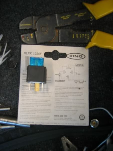
Once you’ve made the wire ID you will need to make a connection from it to terminal 86 on the relay. Rather than completely cut a wire in the loom, I chose to strip a small length of the red/grey wire and make a connection by binding the relay feed wire in place and then making a solder connection to secure it before insulating the whole thing with tape. I chose to fix the relay on the rear boot bulkhead, near the top, beneath the lip to the right (bulkhead centre) of the header tank.
relay ready
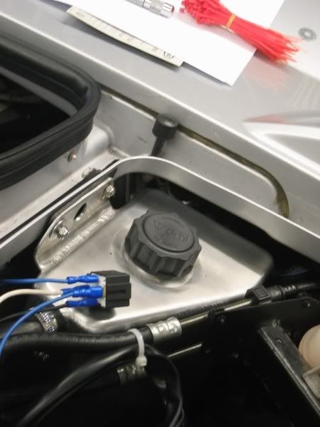
It needs to be where it’s protected from the weather. In my car the Racelogic Traction control unit is also situated on the boot bulkhead and my relay is in the space between that at the header tank. Once the wire is connected you can run it around the corner by the ECU and on to the boot bulkhead to secure it to the boot release catch cable sheath which will run behind the CC header tank.
Relay in place
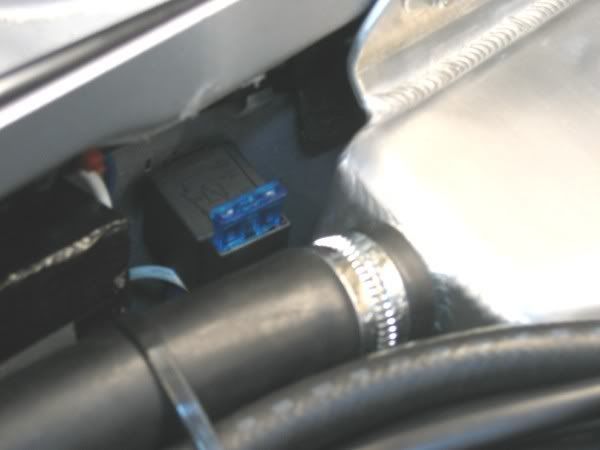
You now need the positive feed from the battery to run up and around the top of the rear wheel arch, and along the boot bulkhead from the offside to terminal 30 of the relay. Somewhere on this run (approx wheel arch centre?) The negative wire from the battery needs to be prepared for connection to the negative terminal of the CC pump.
You need a length of wire (+ blue) from terminal 87 of the relay to the CC pump +, and finally a length of wire (- black) from terminal 85 on the relay to earth. I chose the earth connection on the left hand side (from the rear) of the inlet manifold which is only about a foot from the relay. As my relay had an integral 30 amp fuse, I changed that for 15 amp. Make all relay the connections put the relay in chosen place and tie all cables.
Return to installing the header tank and pump and hoses before the final connections below are made.
Finally all that’s left is connecting the (+) from the relay and the (-) from the battery to the pins that insert into the CC pump plug. This should wait (to determine the final +/_wire lengths) until the pump has been placed in situ. Ensure you plug the plug in the pump and note its orientation in relation to the clearly marked +/- on the pump before removing it to insert the pins in the correct holes.
In the picture you will see I’ve used a white wire (+ from battery) rather than conventional blue because I couldn’t get hold of 7 metres of blue 17 amp cable, Lucas had sold out.
Tape everything up. Because of the location of the pump plug immediately behind the wheel arch liner in a place that may get a lot of indirect moisture, once the plug was in place I also taped over the connection itself to keep out any moisture. Secure wires with ties as required.
Make battery connections.
Installing the Charge Cooler.
Bolt the black bottom angled CC support to the sub frame and tighten the bolt sufficiently so that the support can just be moved with some effort. This will allow it to be finely adjusted for angle without danger of it moving before full tightening.
Picture courtesy of Pro Alloy
Bottom bracket
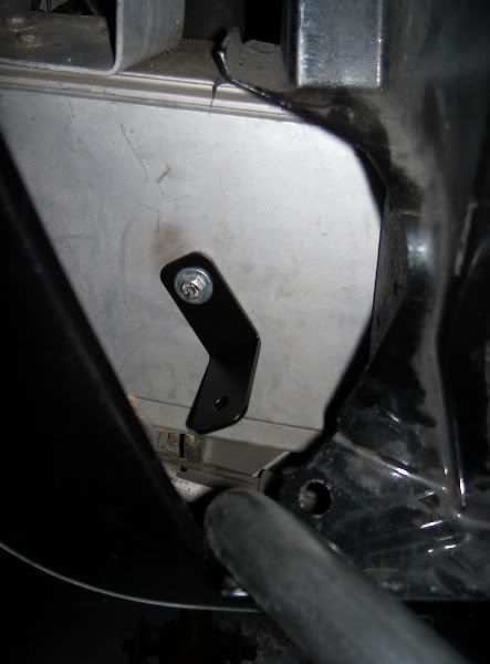
Insert the charge cooler in through the front of the rear wheel arch. It may need to go in and out a couple of times to fit properly. It’s a snug fit and when I first looked I had a slight moment of doubt and wondered if I’d failed to take note of something somewhere that said the rear clam needed to come off to fit it. First time in, the CC fouled the top turbo ear retaining screw so that had to be trimmed back about 3/8ths of an inch. Put the top rear retaining bolt nearest you in place and tighten the nut. I used a similarly sized non nyloc nut just for the fitting check because it’s easy to run it in and off the bolt quickly with your finger. Adjust the CC in and away from the clam by pushing and then from the turbo ear aperture, adjust the angle of the bottom support bracket, inserting the bolt until it threads on the CC.
On my car I found the angle of the lower bracket was not quite correct to allow the bolt to thread properly and I had to bend the bracket slightly in the vice. Then there was a very slight gap which would have distorted the support upon tightening so I shimmed it out with a couple of washers between it and the CC. On cars like this there are bound to be very slight variations like this in fixing orientations.
With the CC out tighten the bottom support bracket to sub-frame nut ensuring you don’t disturb the established correct angle. I marked mine with a line against the sub frame to ensure it didn’t move on tightening.
Bottom bracket
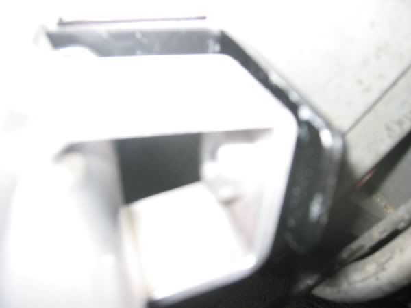
When you’re satisfied the fit is correct, connect the push sensor to the top of the CC and insert holding bolt. I found that the lead for the sensor was too short and had to cut one of the cable ties holding it to the loom for a more flexible fit.
Put the CC back in and tighten all fixings. Push supply hose at front of CC down into the sill area to give small adjustment leeway and mark for cutting against the inlet then cut. With jubilee clip in place push cut rad hose on to inlet. You can ease this procedure on each hose connection if you want by putting the thinnest smear of silicone grease on the outside of the CC connection.
Replace CC air supply hoses top and bottom and tighten jubilee clips.
Header Tank
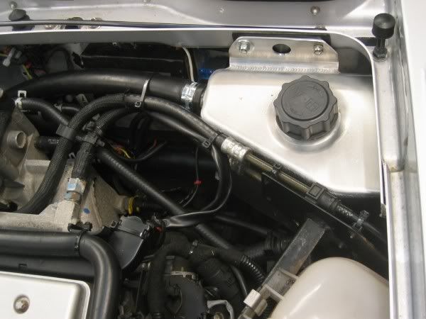
The header tank can be fitted once the relay electrical connection has been made. It fits in the nearside rear corner of the engine bay. Remove the two bonnet stay bolts and using the alternative longer bolts supplied bolt tank in place. Again it’s a snug fit and you may have to push slightly on the VX coolant header tank bracket to get it in, but it fits. The header tank has a bottom flange with a hole. When it’s in place with the two top bolts its easy, from the engine compartment, to make a hole through the boot bulkhead first with a sharp bradawl or similar, and then locate and enlarge it from the other (boot) side to accommodate the fixing bolt and washers.
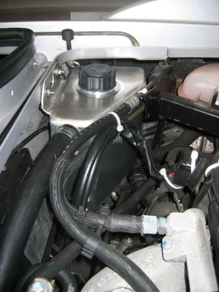
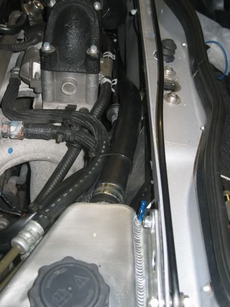
Hose from bottom CC header tank to CC pump
This is the shortest (1000mm) hose. Fix it to the pump rear inlet, (opposite end to the electric plug connection) and secure the jubilee clip. From the wheel arch insert the hose along the side of the boot bulkhead to the header tank bottom outlet. It’s important to get this length right. The pump body (not plug) end needs to be approximately in line with the corner of the boot. There needs to be enough room for the wires from the pump plug to turn at right angle and up, bearing in mind that they will be fairly tight against the wheel arch liner. Mark and cut the hose at least an inch longer than required for a temporary first fit and then shorten as required to ensure accurate length and then remove pump and hose.
Supply hose from CC pump to pre rad
This hose comes up from the sill to the gap rear left of the CC, left of the CC rear connector, and follows up as far as CC top air hose, to run alongside/slightly below. Push hose down in to the sill area to allow leeway for length adjustment. It’s convenient to secure hose temporarily for fit to the CC top air hose with loose cable ties, bearing in mind it needs to run quite high (see pic) over and across for the pump to be situated accurately just forward of the boot bulkhead.
The accurate length of this hose is important. The pump needs to ‘hang’ on it without touching the sub frame beneath and without touching the boot rear bulkhead. If the pump touches either of these when working, the vibration of the pump is hugely amplified and transmitted through the car. (See ‘Pump’ below)
With the hose roughly in place mark and cut long, then trim as required experimenting with hose on pump, and pump supply hose on header tank until the required position is achieved bearing in mind hose length will alter (shorten) when properly secured to the CC top air hose.
CC rear
http://i155.photobuc...mov1/CCrear.jpg
Here the hose(es) are temporarily in place with white cable ties.
Pump
As stated the pump needs to ‘hang’ without touching.
Pump hanging
http://i155.photobuc...pumphanging.jpg
I took the precaution of putting padding between the pump, the boot bulkhead and the sub frame. To do this I used one of the remaining pieces of sponge that came off the original rad. I pushed it in place between the pump and the boot and around beneath to the sub frame and up slightly and cut to length. I cleaned the boot bulkhead and the sub frame surfaces, applied a liberal amount of Bostick multi purpose adhesive to the sponge, lifted the pump and slid the sponge in place.
Care needs to be taken here because on the outer circumference of the pump nearest you there are vents which appear to be for air circulation to the pump motor. The sponge needs to be pushed in beyond these vents so as to ensure this air circulation is not interfered with in any way.
Pump and sponge
http://i155.photobuc...umpandfoam1.jpg
Return hose from CC bottom rear to header tank top connection
Connect hose to CC bottom rear outlet. Initially it follows the pump hose up to CC air hose and then beneath it as it curves around, breaking away to rise diagonally alongside the boot bulkhead to the to header tank return connection. Loosely tie in place, mark and cut long before final cut and connection. Tighten jubilee clips; tighten cable ties to secure hose where convenient
Supply and return hoses from front wheel arch to pre-rad.
Push both hoses into sill, before measure, mark and cut. These hoses need to come around up and over the front wheel arch liner so the curve/fit is slightly longer than the tightest curve you can achieve. Pushing the hoses down into the sill will give you the extra length adjustment if you need it when you come to actually replace the liner.
hoses front
http://i155.photobuc.../Hosesfront.jpg
Filling with coolant
With all hose in place and all jubilee clips secured the system was ready to be filled. As before red coolant 50/50 water. You may consider adding a wetting agent at this point to wring the maximum heat exchange properties from the system fluid. I didn’t, your choice. My system took fourteen pints in total to fill, but not until the pump had circulated the air out, so fill as far as you can. I used the top of the coolant return inlet as a marker. This deliberately protrudes inside the header tank so it can be seen with the cap off. Allow some time to settle.
Commissioning the system
With the header tank cap off, turn the ignition switch but do not start the engine. The pump (assuming the electrics are in order) will initially make a loud screeching noise as it attempts to pump but is grabbing mainly air and little fluid. I’m sure this doesn’t do the pump much good so I only allowed it to turn for a few seconds bearing in mind that even after the ignition is shut off it will still run for five/six seconds.
Check the coolant level in the header tank, if it has fallen top up.
Repeat ignition on etc.
After doing this twice my pump then started to grab fluid and the noise lessened as did the revs of the pump although there was obviously still a lot of air there, and I let it run for about 20 seconds the switched off.
The header tank was nearly empty so I topped it up.
Again I turned on the ignition, but this time started the engine and switched off leaving the pump to run. I placed my fingers inside the header tank filler hole and repeatedly blocked and unblocked the protruding top return pipe to create a backpressure against the pump to encourage the coolant to circulate upon the pressure release.
This was effective and finally coolant began to flow back through the system. Below you can see it flowing through the header tank inlet
Header tank fluid
http://i155.photobuc...ertankfluid.jpg
There was lots of air and the header tank had to be repeatedly topped up. The bottom lip of the coolant supply pipe inside the tank is a good level indicator.
The pump becomes noticeably quieter as less and less air circulates in the system.
Continue until the system level remains stable, bearing in mind that as with the main VX cooling system it may need topping up again once the car is run on the road.
Reassemble the car
You may find the two wheel arch liners need a little more care/adjustment to first because of the new hoses, but it shouldn’t be a problem. Also access to the retaining nut on the offside headlight is now tight. Rather than using the original nyloc nuts on my headlights I have replaced them some time ago with ordinary stainless steel nuts and a split washer. This makes it easy to run the nuts quickly down the thread with your finger and in this situation with the newly restricted access; only having to use a spanner for the final tightening turn was very helpful.
Time
I’ve no idea how long this project took in hours but making it up as you go along means that things tend to proceed slowly. I like to do things thoroughly like tinning wire ends with solder before making the crimp connections, chasing tight/rusted threads with tap and die, etc. I was at it on and off for ten days in total but this included days where I worked 11 hour shifts and had little time to do anything on the car and a complete day off. The weather was fantastic and sun scorching the whole time. I suspect for one competent person with instructions it’s a 3 day job.
On the road
Drive the car keeping an eye on the temp gauge and coolant level indicator. Check CC header tank also.
Weight
The CC system weighs just under 40 lbs. With 14 pints of fluid that comes to a total of around 57 lbs. To offset this I’ve gained 15 lbs elsewhere, but the car is still 40 odd lbs heavier which is a lot. I can’t say I notice a difference in performance with this extra weight, perhaps it’s offset by consistently cooler induction temperatures. The temp gauge consistently shows one degree less than before. Do I need I need a remap?
Big Thanks
To Pro Alloy and in particular Alex Os who went well out of his way to provide assistance and suggestions during this project. Thanks Alex.
Finally
I get a childish satisfaction from listening to the pump quietly whirring as I walk away from the car.

Edited by oblomov, 08 May 2007 - 07:16 PM.
