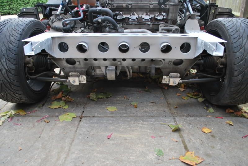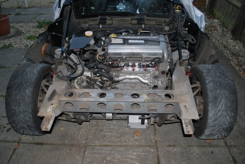
My New Project
#381
Posted 26 September 2009 - 09:08 PM
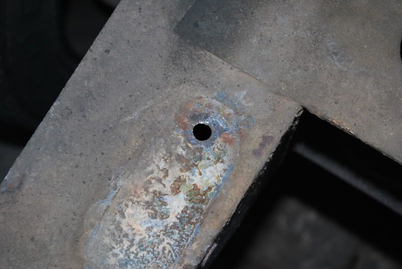
Also dremelled out the failed clam to boot fixings, to be replaced with stainless rivnuts
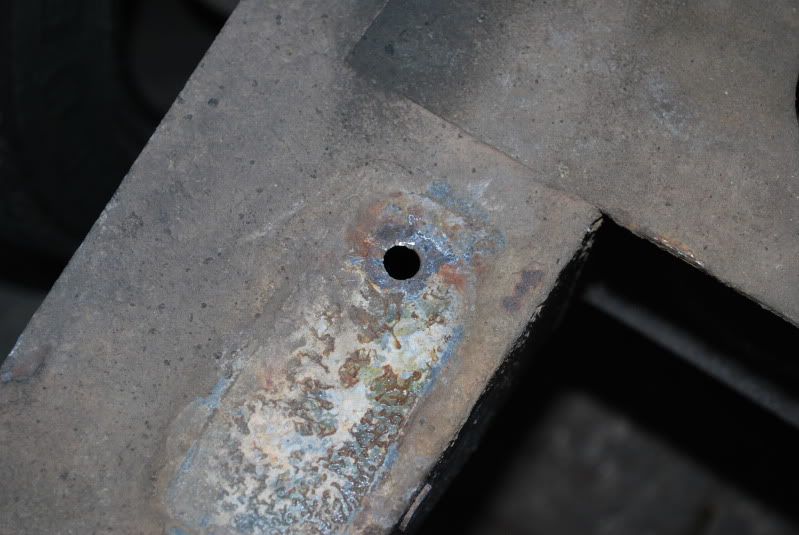
The manifold crack all but dissapeared after I'd slackened off the studs
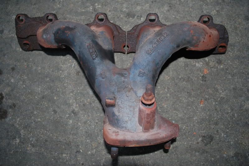
I'll give everything a good clean tomorrow I think
#382
Posted 26 September 2009 - 09:31 PM
#383
Posted 26 September 2009 - 09:40 PM
Not really I'll have a good poke around for you tomorrow thoadam, is there anything in the corner, behind drivers seat that can rattle alot? Got a bitch of a rattle, comes on about 3k rpm. Very tinny, doesnt sound like it comes from engine bay...
It's very easy to lose seat belt bolts or spacers down there? Have your seatbelts ever been removed (for a harness bar etc)
#384
Posted 27 September 2009 - 03:22 AM
#385
Posted 27 September 2009 - 08:42 PM
#386
Posted 27 September 2009 - 08:45 PM
#387
Posted 29 September 2009 - 12:50 PM
#388
Posted 29 September 2009 - 12:53 PM
#389
Posted 29 September 2009 - 12:56 PM
seat, belts, nope - nothing ever been removed
TBH, i was hoping to get some ideas before i spend a few hours removing it all and end up with 2 rattles
Paul your seatbelt bolts are loose certainly the pax one is
DG
#390
Posted 29 September 2009 - 04:25 PM
seat, belts, nope - nothing ever been removed
TBH, i was hoping to get some ideas before i spend a few hours removing it all and end up with 2 rattles
Paul your seatbelt bolts are loose certainly the pax one is
DG
I would try to do them up but some fcuker STILL has my socket wrench!
#391
Posted 29 September 2009 - 06:24 PM
Around 4 hourscome on then how long did it take to get the rear clam off?!
#392
Posted 04 October 2009 - 06:30 PM
First thing was to remove the old bolts/rivnuts - I made lots of slots across the top of the fastener with a Dremel cutting disc, then used a screwdriver an hammer to fold the remains in, until they simply dropped through, then left with this after prising the glued on plates off:
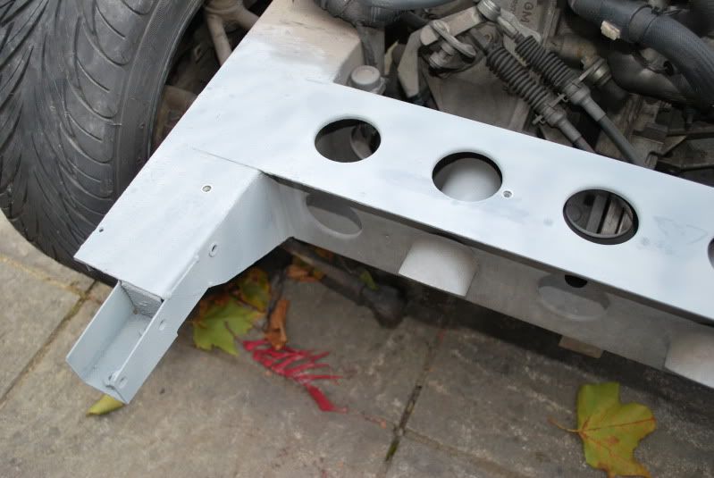
Gave everything a good clean with a drill mounted wire brush, then a coat of zinc primer (90% zinc)
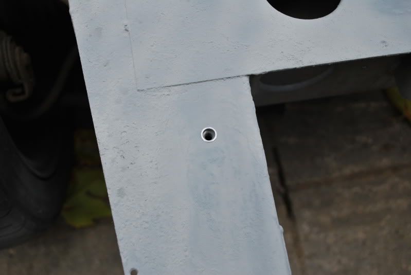
And added some stainless steel M6 Rivnuts [available on ebay, but you also need the Rivnut tool]
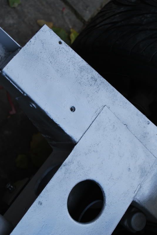
Then a coat of Silver paint to keep the zinc primer in place
#393
Posted 04 October 2009 - 06:44 PM
Due to lack of instructions and little info on here I've taken a load of pics whilst fitting the toe link kit
The Spitfire kit is extremely well made (I was dubious whether it was really worth all that money, but I'm happy to say I think it is - no corners cut here)
Obviously I've done this with the rear clam already off, no doubt it would be much harder if it were in place, especially when drilling the holes as the exhaust may well get in the way!
Worth noting that this is my interpretation of fitting, there may well be an easier way
Tools:
Jack
Support
Wheel Brace
2 x 19mm spanners
2 x 17mm spanner
12mm spanner
10mm spanner
5mm socket mounted allen key
6mm socket mounted allen key
17mm socket
15mm socket
12mm socket
Electric Drill
Good quality drill bits
Goggles
High temp grease
Dremel and cutting discs (possibly) or second jack
Adjustable wrench
Centre punch
Large hammer
Small hammer
(and I've probably missed things off!)
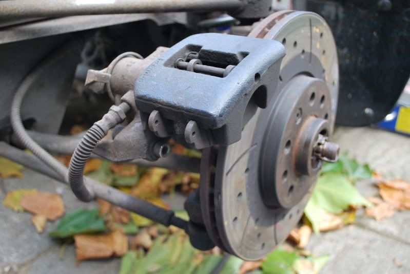
To start with jack up the car and support on one side, remove rear wheel
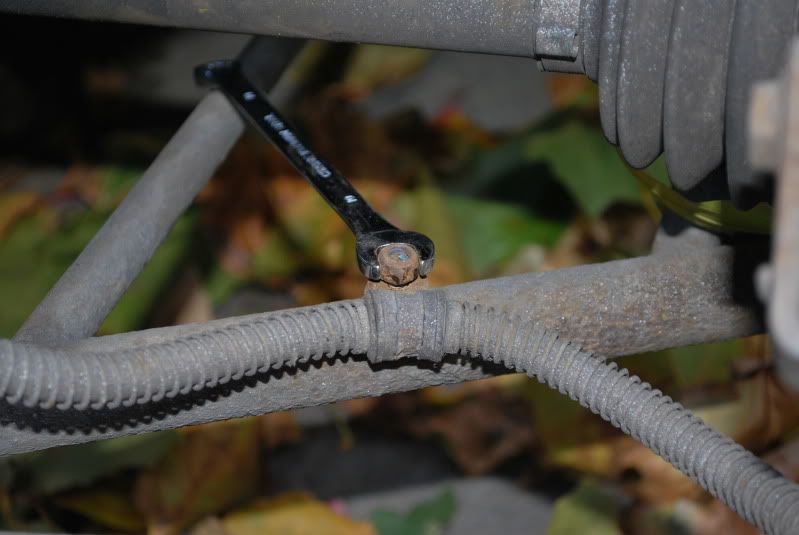
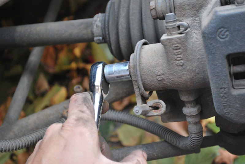
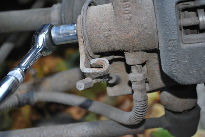
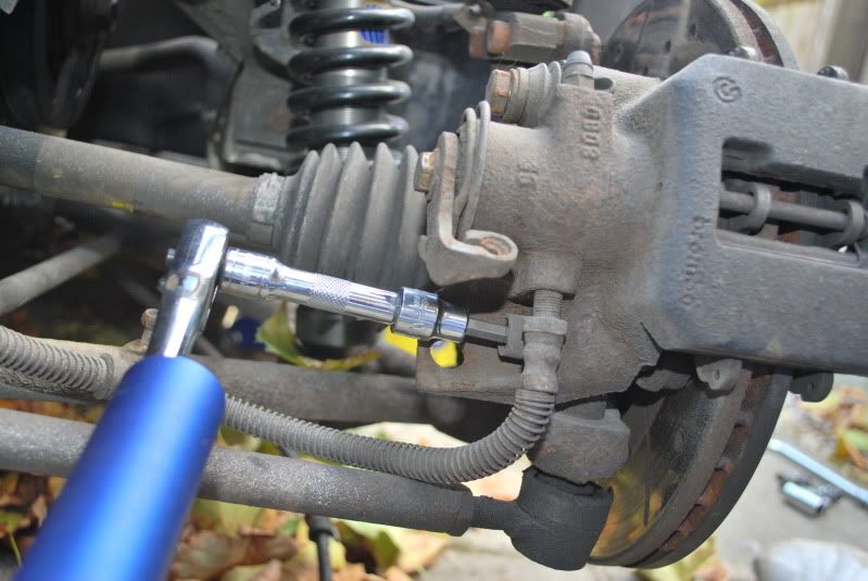
Undo the brake line and handbrake retaining bolts on the wishbone (they may look like they'll never budge, but they will with a bit of force)
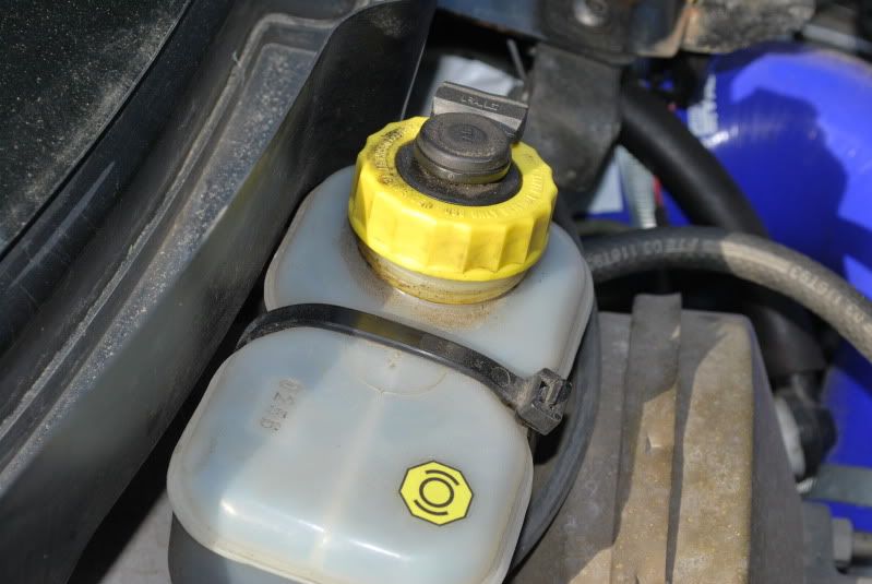
Loosen cap on brake fluid resevoir
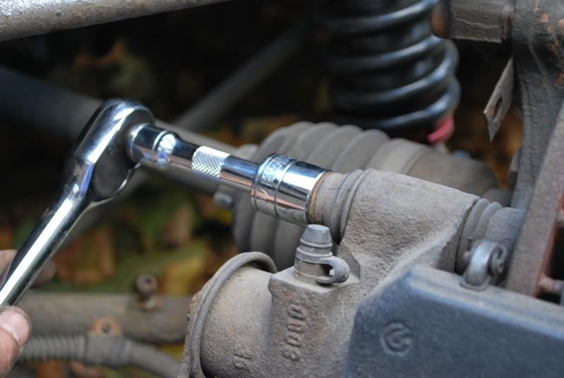
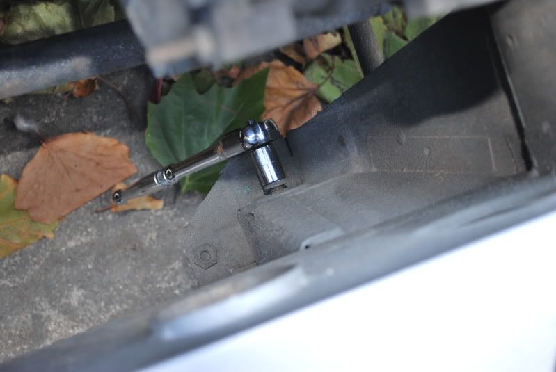
Use a socket on the handbrake mechanism nut to activate the movement, so the handbrake cable becomes loose
You should be able to pop the handbrake cable free I had already slackened the adjuster off beneath the undertray, as I plan to replace the cable next week; if there isn't enough movement in the adjuster arm you'll need to remove the large rear undertray and fiddle with the adjuster
Then loosen the top caliper bolt (this may require a bit of force - I used a jack handle to give extra leverage)
And using a 6mm allen bit remove the lower bolt
#394
Posted 04 October 2009 - 06:52 PM
#395
Posted 04 October 2009 - 06:57 PM
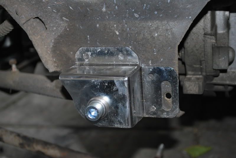
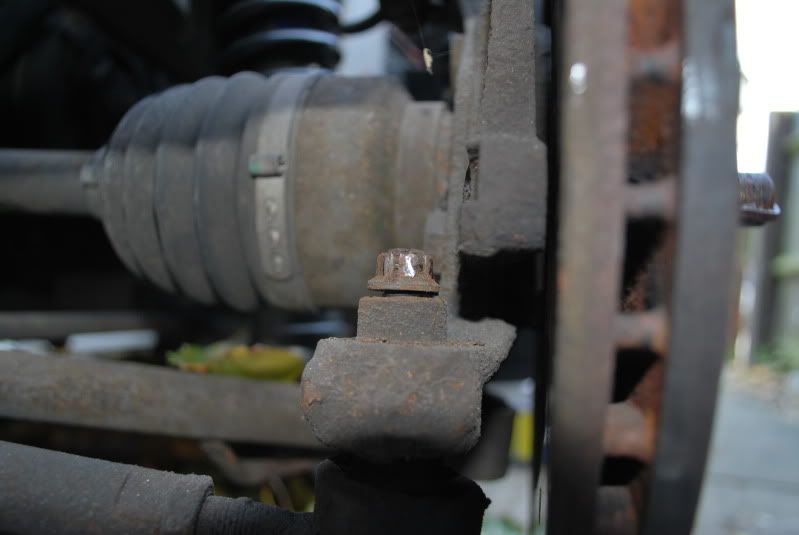
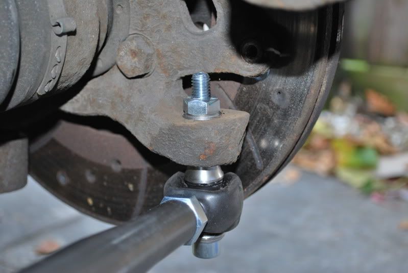
Removing this nut can be done in a few ways - you can try to get a spanner onto the flats on the ball joint side (I didn't have one that would fit); you can place a jack under the balljoint to stop the joint simply spinning (no matter what position I tried with the jack, it just kept spinning); or last resort is to use a Dremel to make a cut either side of the nut - it will then come off easily
Then remove the other end, by undoing the wishbone bolt from the engine bay side, and tapping through with a hammer
Now set the length of the new arm to that of the existing, from balljoint to balljoint
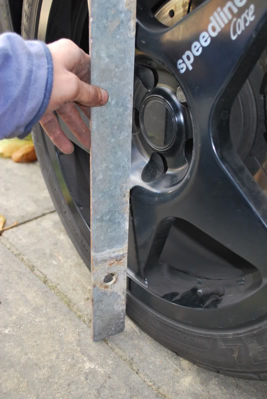
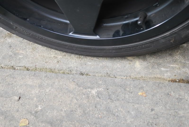
I also marked the floor before removing the wheel using a flat peice of steel against the wheel, you can then compare against these marks later
#396
Posted 04 October 2009 - 06:57 PM
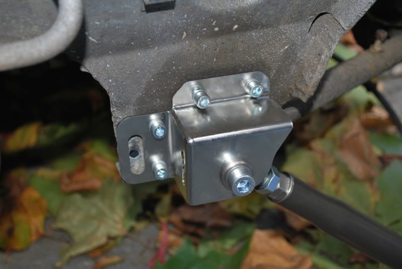
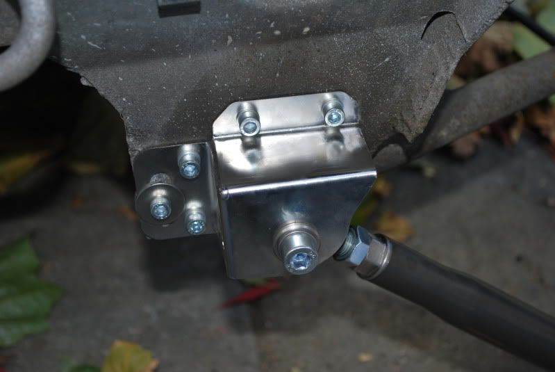
Then use a centre punch and lump hammer to marke the place to drill. Use a series of drills to make the holes, checking alignment each time - I used 3mm, 4.5mm then 6mm
Pull back the gaitors on the each end of the tie rods and use some high temperature grease to smear around the rose joint
Then bolt it all together - very fidly trying to get the top bolts in place!
I also used a fifth bolt, just for extra peace of mind, as there is already a hole in the subframe
Then connect the outboard side up - I'm presuming I've done this right
Obv the tubby is slightly different as later ones have a taper joint
And all done, refitting is essentially the reverse of the above
Make sure you pump the brake pedal a few times after replacing the cap!!!
#397
Posted 04 October 2009 - 06:58 PM
This is classed as maintenancelooks good mate and you making progress now , will there be a time when your car is finished lol
#398
Posted 04 October 2009 - 07:05 PM
This is classed as maintenancelooks good mate and you making progress now , will there be a time when your car is finished lol
lol is that what it is
#399
Posted 04 October 2009 - 07:05 PM
#400
Posted 04 October 2009 - 07:06 PM
Dohyou should have measured the distance between the disc face and chassis
I used a steel ruler and a tape measure, there is a lip at the bottom of the chassis (where the subframe bolts to the chassis) the distance between that lowest lip and the outer face of the disc was 176mm on mine
I did point out at the beginning there are probably better ways
2 user(s) are reading this topic
0 members, 2 guests, 0 anonymous users