Comming along nicely, mostly just got the wiring to do now. Anyone else have to shave a small amount off the top of the inlet manifold? It wouldn't fit because it hit a small bit on the head so I had to shave a mil or so off the top.
Does anyone have pics of how they've run the fuel lines? At the moment I'm running them between the S/C and alternator but am a little concerned this is a bit too close to the belt route.
Also I can't figure out what the dipstick relocation bracket is supposed to attach to?

Stage 2 Sc Conversion
Started by
vocky
, Sep 25 2009 05:34 PM
284 replies to this topic
#201

Phear
-

-

- 1,125 posts
Need to get Out More
- Gender:Male
- Location:Bromsgrove
Posted 06 March 2010 - 05:33 PM
#202
Silky
-

-
- 70 posts
Member
- Gender:Male
- Location:norwich
Posted 06 March 2010 - 05:43 PM
Comming along nicely, mostly just got the wiring to do now. Anyone else have to shave a small amount off the top of the inlet manifold? It wouldn't fit because it hit a small bit on the head so I had to shave a mil or so off the top.
Does anyone have pics of how they've run the fuel lines? At the moment I'm running them between the S/C and alternator but am a little concerned this is a bit too close to the belt route.
Also I can't figure out what the dipstick relocation bracket is supposed to attach to?
i all so had to take a little off the inlet to get it on
my fuel lines run under the charger the first bracket they bolt to all i did was undo this and bolt them to the other side and stops the going any where near the belt with out having to change the other part at all
hope this helps if not i can take pictures tomorrow if needed
#203
Phear
-
-
- 1,125 posts
Need to get Out More
- Gender:Male
- Location:Bromsgrove
Posted 06 March 2010 - 05:50 PM
my fuel lines run under the charger the first bracket they bolt to all i did was undo this and bolt them to the other side and stops the going any where near the belt with out having to change the other part at all
It sounds like the same route as mine, but if you could pop a pic up i'd appreciate it

Can you shed any insight on the dipstick bracket?
#204
vocky
-
-

- 11,969 posts
Moderator
- Gender:Male
- Location:Earth
Posted 06 March 2010 - 05:54 PM
dipstick bracket uses the passenger sc mounting bolt, very fiddly  fuel lines need to clear the belt and be secured so there is no risk of them ever being damaged
fuel lines need to clear the belt and be secured so there is no risk of them ever being damaged
#205
Phear
-
-
- 1,125 posts
Need to get Out More
- Gender:Male
- Location:Bromsgrove
Posted 06 March 2010 - 06:00 PM
dipstick bracket uses the passenger sc mounting bolt, very fiddly
fuel lines need to clear the belt and be secured so there is no risk of them ever being damaged
Right I think I get what you mean, that does sound like fun.
I understand the dangers of running the fuel lines but I can't find a route thats i'm 100% happy with and wanted to see what others were doing.
#206
Exmantaa
-
-
- 3,982 posts
Scary Internerd
- Gender:Male
Posted 06 March 2010 - 06:18 PM
Saw a pic somewhere where both fuel lines were rerouted directly from the rail.
Hardlines cut and pressure hose directly routed to the pump etc.
Avoids the belt completely. 
#207
Phear
-
-
- 1,125 posts
Need to get Out More
- Gender:Male
- Location:Bromsgrove
Posted 06 March 2010 - 06:42 PM
Saw a pic somewhere where both fuel lines were rerouted directly from the rail.
Hardlines cut and pressure hose directly routed to the pump etc.
Avoids the belt completely.
I agree its the best solution, however the though of cutting those lines fills me with dread, maybe i'll grow a pair and give it a try!
#208
Seb.F
-
-

- 6,045 posts
Under Your Bed
- Gender:Male
- Location:Northants
- Interests:Tech head
Posted 08 March 2010 - 07:21 PM
Anyone know how to remove the Laminovas from the manifold... mine don't seem to want to move!
#209
leevx2.2
-

-
- 4,830 posts
Turbo's are for girls and throttle bodies are too slow
- Gender:Male
- Location:Bedford
-
Interests:Taking apart vx220s for fun
getting p!!sed
genraly playing with large power tools
Posted 08 March 2010 - 08:03 PM
what i done to mine just cut them and get some fuel pipe and reposition
Saw a pic somewhere where both fuel lines were rerouted directly from the rail.
Hardlines cut and pressure hose directly routed to the pump etc.
Avoids the belt completely.
I agree its the best solution, however the though of cutting those lines fills me with dread, maybe i'll grow a pair and give it a try!
#210
Seb.F
-
-
- 6,045 posts
Under Your Bed
- Gender:Male
- Location:Northants
- Interests:Tech head
Posted 08 March 2010 - 08:11 PM
But but, Laminovas!
#211
Sutol
-

-
- 8,121 posts
Well it's nearly a Lotus
- Gender:Male
- Location:Billingshurst, West Sussex
Posted 08 March 2010 - 09:21 PM
Seb refer to my fotos a few pages back. Small pair of pliers and use on the thicker radial sections. Pull out firmly, there is nothing holding them in apart from grime and an 'O' ring. leave overnight in degreaser. Make sure you put them in the right way round depending on single pass or double pass. I changed the 'O' rings on mine as precaution.But but, Laminovas!
#212
Seb.F
-
-
- 6,045 posts
Under Your Bed
- Gender:Male
- Location:Northants
- Interests:Tech head
Posted 08 March 2010 - 10:21 PM
Got them!
Cheers
#213
Mike (Cliffie)
-

-
- 13,353 posts
Back in a VX
- Gender:Male
- Location:North Yorkshire
- Interests:Weaving weasels woolly hats.
Posted 09 March 2010 - 10:10 AM
Just getting the last of the bits together and I ave some other Q's:
1) What exactly is the Corsa Top Hose? I can deduce its from a Corsa and its connects to the top of something but I want to try and find one at a scrappies/breakers and I need to know what I'm looking for. What model corsa and which hose specifically is it? And what part does it play in the conversion?
2) My inlet manifold has MAP sensor on it (I presume its a MAP sensor). Now the parts list contains a "Top Map Sensor Blanking Plate" and a new MAP sensor. If the blanking plate is for the existing one, where does the new one go? Also I presume the N/A doesn't as standard have a MAP sensor? Only a MAF, so how does the MAP sensor wire into the ECU?
3) What goes in the "Alloy Joiner with Offset Temperature Sensor Socket"? I presume a themostat of some kind, but theres no stat on the list of parts?
I think I can figure out what everything else on the list is for, except perhaps the "Inlet Manifold Alignment Bungs" and "50mm Grommets" but I'm hoping those will make sense once I get started
Cheers
Phil
1) You need to mod the waterhose coming from the head. The SC snout will foul this hose, so you need to cut it and fit a different bend with a piece of alu tubing/clamps. Probably the alloy joiner 3) with temp sensor offset is used here and that temp sensor is used to start the fans at a lower temperature.
2) LSJ manifold has originally a TMAP sensor fitted. This needs to be changed for the Courtenay (2 bar?) Delphi MAP sensor. (Similar to the NA's 1 bar version.) You will need to bodge something so it fits into the wider TMAP hole. (I removed the orange seal, fitted a thin piece of rubber tube to thicken it up, refitted the orange seal over this and now it fits snug into my manifold. Plus a small bracket to secure it.)
The SC on the LSJ engine also has a "Super Charger Inlet Pressure" sensor fiitted on top. This hole must be blanked off in the 2,2 conversion. (I used it to connect the Petrol EVAP cannister hose...)
3) see 1)
The LSJ SC manifold is cast for the Saab head with 8mm studs. The 2,2 head has 6mm studs, so 2 allignment bungs (simple 6->8mm alu tube piece) are used to center the manifold on our heads.
50mm grommets? Can only think of grommets for the 19/28mm water hose through the sills...
Good luck!
Here is my tuppence worth.
Run the charge cooler pipes up the passenger side... easier, closer to the header tank, the inlet take offs are on that side and it saves running the pipes across the engine bay.
Have the header tank as hot so the hot runs fron the inlet to the top of the header. Then out the bottom and through the pump, then to the charge cooler and finally back to the inlet.
Use Kawasaki manifold studs, they are 6mm/8mm and work perfectly. Lee2.2VX knows more.
Send your ECU off to Courtenay for a base map, much easier than running tandem injector plugs.
Buy a loom from ZZP in the US for the injectors, makes life far more pleasant when wiring and only £30 delivered, you will spend £40 for the original Bosch ones from Vauxhall.
When priming the charge cooler pump it helps to pressurise the system, I used my lungs...
The Temp sensor thingy... I bought one from Demon Tweeks, it is a bit pricey but gives total control over the temp the fans cut in. Worth it in my opinion.
There are far more bits needed than are on RC Vaughan's list.
Have faith, it is easier than you think but have patience it takes longer than you think as well.
Hope this helps.
This wont work with the Pro Alloy pre rad as the fans are off set and the rad will only fit one way in the crash box and this is with the inlet/outlet on the O/S
Unless you want a big loop of tubing running round the front of the car.
Shame though as it would save the need for so much piping

That is why I didn't use the Pro Alloy charge cooler.
Edited by Cliffie, 09 March 2010 - 10:10 AM.
#214
Jameshs
-

-
- 3,511 posts
Scary Internerd
- Gender:Male
- Location:Copthorne, Nr Gatwick
- Interests:Cars and Rock Climbing
Posted 09 March 2010 - 03:16 PM
Just getting the last of the bits together and I ave some other Q's:
1) What exactly is the Corsa Top Hose? I can deduce its from a Corsa and its connects to the top of something but I want to try and find one at a scrappies/breakers and I need to know what I'm looking for. What model corsa and which hose specifically is it? And what part does it play in the conversion?
2) My inlet manifold has MAP sensor on it (I presume its a MAP sensor). Now the parts list contains a "Top Map Sensor Blanking Plate" and a new MAP sensor. If the blanking plate is for the existing one, where does the new one go? Also I presume the N/A doesn't as standard have a MAP sensor? Only a MAF, so how does the MAP sensor wire into the ECU?
3) What goes in the "Alloy Joiner with Offset Temperature Sensor Socket"? I presume a themostat of some kind, but theres no stat on the list of parts?
I think I can figure out what everything else on the list is for, except perhaps the "Inlet Manifold Alignment Bungs" and "50mm Grommets" but I'm hoping those will make sense once I get started
Cheers
Phil
1) You need to mod the waterhose coming from the head. The SC snout will foul this hose, so you need to cut it and fit a different bend with a piece of alu tubing/clamps. Probably the alloy joiner 3) with temp sensor offset is used here and that temp sensor is used to start the fans at a lower temperature.
2) LSJ manifold has originally a TMAP sensor fitted. This needs to be changed for the Courtenay (2 bar?) Delphi MAP sensor. (Similar to the NA's 1 bar version.) You will need to bodge something so it fits into the wider TMAP hole. (I removed the orange seal, fitted a thin piece of rubber tube to thicken it up, refitted the orange seal over this and now it fits snug into my manifold. Plus a small bracket to secure it.)
The SC on the LSJ engine also has a "Super Charger Inlet Pressure" sensor fiitted on top. This hole must be blanked off in the 2,2 conversion. (I used it to connect the Petrol EVAP cannister hose...)
3) see 1)
The LSJ SC manifold is cast for the Saab head with 8mm studs. The 2,2 head has 6mm studs, so 2 allignment bungs (simple 6->8mm alu tube piece) are used to center the manifold on our heads.
50mm grommets? Can only think of grommets for the 19/28mm water hose through the sills...
Good luck!
Here is my tuppence worth.
Run the charge cooler pipes up the passenger side... easier, closer to the header tank, the inlet take offs are on that side and it saves running the pipes across the engine bay.
Have the header tank as hot so the hot runs fron the inlet to the top of the header. Then out the bottom and through the pump, then to the charge cooler and finally back to the inlet.
Use Kawasaki manifold studs, they are 6mm/8mm and work perfectly. Lee2.2VX knows more.
Send your ECU off to Courtenay for a base map, much easier than running tandem injector plugs.
Buy a loom from ZZP in the US for the injectors, makes life far more pleasant when wiring and only £30 delivered, you will spend £40 for the original Bosch ones from Vauxhall.
When priming the charge cooler pump it helps to pressurise the system, I used my lungs...
The Temp sensor thingy... I bought one from Demon Tweeks, it is a bit pricey but gives total control over the temp the fans cut in. Worth it in my opinion.
There are far more bits needed than are on RC Vaughan's list.
Have faith, it is easier than you think but have patience it takes longer than you think as well.
Hope this helps.
This wont work with the Pro Alloy pre rad as the fans are off set and the rad will only fit one way in the crash box and this is with the inlet/outlet on the O/S
Unless you want a big loop of tubing running round the front of the car.
Shame though as it would save the need for so much piping
That is why I didn't use the Pro Alloy charge cooler.
What did you go for in the end??
#215
Seb.F
-
-
- 6,045 posts
Under Your Bed
- Gender:Male
- Location:Northants
- Interests:Tech head
Posted 09 March 2010 - 03:16 PM
Holy sh** batman HUGE quotes 
#216
Phear
-
-
- 1,125 posts
Need to get Out More
- Gender:Male
- Location:Bromsgrove
Posted 14 March 2010 - 02:21 PM
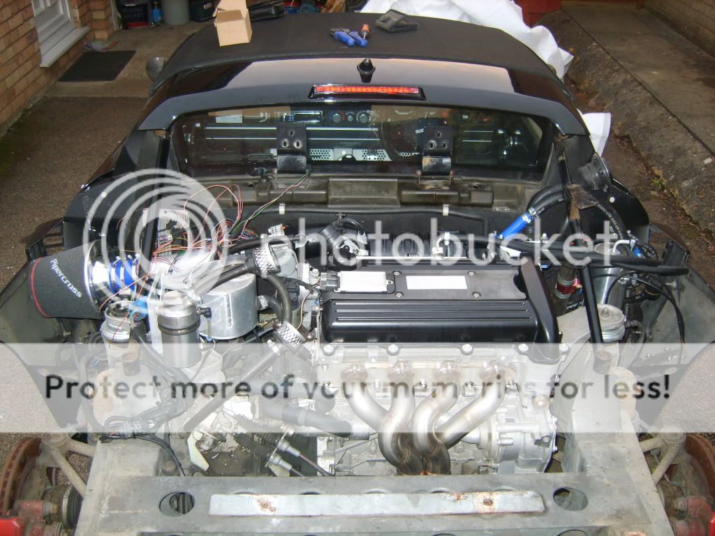
Well the first major milestone has been reached, I started her today Started first push of the button (once I'd realised I hadn't reconnected the fuel pump relay). I've still got to fill up the charge cooler system (and check the pump works) and I now need to order a full 3" exhaust system and fit that too.
I had an EML when I first started her and Op-Com indicated P1512, something about TPS. I cleared the code, re-started her and it didn't seem to come back, should I be concerned?
Here is a pic of my fuel lines at the mo, still debating what to do but I like the look of what Lee has done!
[attachment=21841:DSCN0636.JPG]
Started first push of the button (once I'd realised I hadn't reconnected the fuel pump relay). I've still got to fill up the charge cooler system (and check the pump works) and I now need to order a full 3" exhaust system and fit that too.
I had an EML when I first started her and Op-Com indicated P1512, something about TPS. I cleared the code, re-started her and it didn't seem to come back, should I be concerned?
Here is a pic of my fuel lines at the mo, still debating what to do but I like the look of what Lee has done!
[attachment=21841:DSCN0636.JPG]
#217
Sutol
-
-
- 8,121 posts
Well it's nearly a Lotus
- Gender:Male
- Location:Billingshurst, West Sussex
Posted 17 March 2010 - 09:45 AM
CS had the car on the dyno yesterday and it achieved just over 250bhp @ 7k. However there is a problem. It leaned off after 6k due to poor fuel pressure. Solution - new fuel pump. Still at least i know that I can't give it the beans yet. This will mean that it will have to be checked out again on the dyno which means another haul up to CS. Got some TD's coming up and CS have said that they will be able to provide a pump and fixing collar very soon - fingers crossed then. I know your pain techieboy (well not completely just some of it  )
)
)
#218
techieboy
-

-
- 22,914 posts
Supercharger of Doom
- Gender:Male
- Location:Bedford
Posted 17 March 2010 - 10:02 AM
 Oh well, at least there's now a decent solution thanks to Cliffie and Glencoe. Just need ProAlloy to do their bit. I must crack on and get my new pump and fuel lines installed as I'm over at North Walsham next week for a health check on the dyno. Will be good to get my missing rpm's restored one of these days.
#219
Mike (Cliffie)
-
-
- 13,353 posts
Back in a VX
- Gender:Male
- Location:North Yorkshire
- Interests:Weaving weasels woolly hats.
Posted 17 March 2010 - 10:35 AM
CS had the car on the dyno yesterday and it achieved just over 250bhp @ 7k. However there is a problem. It leaned off after 6k due to poor fuel pressure. Solution - new fuel pump. Still at least i know that I can't give it the beans yet. This will mean that it will have to be checked out again on the dyno which means another haul up to CS. Got some TD's coming up and CS have said that they will be able to provide a pump and fixing collar very soon - fingers crossed then. I know your pain techieboy (well not completely just some of it
Well done Chris, good to hear it is in and working.
I have the pump kit fitted and will know next week what the outcome will be as am at CMS on 24th.
#220
siztenboots
-

-
- 26,613 posts
RaceMode
- Gender:Not Telling
- Location:Surrey
- Interests:french maids
Posted 17 March 2010 - 10:41 AM
did we ever agree about 2.2 fuel pumps being different to LET?


1 user(s) are reading this topic
0 members, 1 guests, 0 anonymous users

