Jump to content


Photo

Big Power Vxt Project


  • Please log in to reply
4722 replies to this topic

#161 Nev

Nev

    Nipper's Minion

  • PipPipPipPipPipPipPipPip
  • 11,587 posts
  • Gender:Male
  • Location:Bristol
  • Interests:Rock climbing, skiing, kayaking, surfing, mountaineering, budgies, chess, practical mechanics.

Posted 12 December 2010 - 10:28 PM

Picked up the Garrett GTX3071 turbo up today and also the enlarged throttlebody arrived in the post as well. Pics and info here

Hopefully the CMS cast iron manifold will arrive tomorrow. I am growing nervous about this things ability to flow enough for my needs as the T2 flange on it may be a restriction...

#162 The Batman

The Batman

    Super Moderator

  • 30,267 posts
  • Gender:Male
  • Location:FLD mum's bed

Posted 12 December 2010 - 10:33 PM

I will try and dig the part number out tomorrow for that peaches tb, it's 70mm and less than Half te price that you paid for that enlarged one. Although don't think you will need a 70mm one...

#163 Nev

Nev

    Nipper's Minion

  • PipPipPipPipPipPipPipPip
  • 11,587 posts
  • Gender:Male
  • Location:Bristol
  • Interests:Rock climbing, skiing, kayaking, surfing, mountaineering, budgies, chess, practical mechanics.

Posted 12 December 2010 - 11:12 PM

I only paid £120 for the TB work to be carried out ;)

#164 siztenboots

siztenboots

    RaceMode

  • 26,611 posts
  • Gender:Not Telling
  • Location:Surrey
  • Interests:french maids

Posted 17 December 2010 - 09:47 AM

Picked up the Garrett GTX3071 turbo up today and also the enlarged throttlebody arrived in the post as well. Pics and info here

Hopefully the CMS cast iron manifold will arrive tomorrow. I am growing nervous about this things ability to flow enough for my needs as the T2 flange on it may be a restriction...


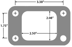
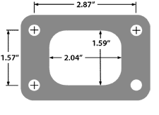
t2 is a bit tame, i thought that was only for the gt2876r ?
Posted Image

t3 by comparison
Posted Image

gtx3071r
Posted ImagePosted Image
Posted Image

#165 Nev

Nev

    Nipper's Minion

  • PipPipPipPipPipPipPipPip
  • 11,587 posts
  • Gender:Male
  • Location:Bristol
  • Interests:Rock climbing, skiing, kayaking, surfing, mountaineering, budgies, chess, practical mechanics.

Posted 17 December 2010 - 07:07 PM

Yea, the T2 flange on the CMS cast manifold is a bit small for the mid sized turbos. They only intended it for the smaller end of the market (approx 300 to 420 BHP), using GT28 CHRAs. My original intention was to use a T2 to T3 adapter flange to fit between the manifold and turbo to address the issue. However, as I am now getting a Nortech tubular manifold built instead, I will be selling the CMS cast manifold on for someone who wants a less powerful build.

Anyway, I went into the garage tonight (brrrr...!) and took some pics of the manifold on a block with the turbo offered up...

Lots of juicy turbo pics HERE

#166 KurtVerbose

KurtVerbose

    His Serene Highness

  • PipPipPipPipPipPip
  • 3,791 posts
  • Gender:Male
  • Location:Merlischachen
  • Interests:Big baps.

Posted 17 December 2010 - 08:27 PM

Lots of juicy turbo pics HERE


That's not fair. Tempt us with the promise of lots of juicy turbo pics and then give the wrong link.

Did you mean this link?

#167 Nev

Nev

    Nipper's Minion

  • PipPipPipPipPipPipPipPip
  • 11,587 posts
  • Gender:Male
  • Location:Bristol
  • Interests:Rock climbing, skiing, kayaking, surfing, mountaineering, budgies, chess, practical mechanics.

Posted 17 December 2010 - 08:51 PM

God I'm stupid, yes you are of course right Kurt. Shame on me not even knowing my own website URL ! :blush:

#168 Nev

Nev

    Nipper's Minion

  • PipPipPipPipPipPipPipPip
  • 11,587 posts
  • Gender:Male
  • Location:Bristol
  • Interests:Rock climbing, skiing, kayaking, surfing, mountaineering, budgies, chess, practical mechanics.

Posted 30 December 2010 - 05:41 PM

The Nortech exhaust manifold has landed... juicy pics here.

#169 Duncan VXR

Duncan VXR

    Scary Internerd

  • PipPipPipPipPipPip
  • 5,277 posts
  • Gender:Male
  • Location:Lincolnshire
  • Interests:Anything to do with making cars faster and better than the original

Posted 30 December 2010 - 06:30 PM

Looks like it could work well nev. Any reason for not seperating the manifold face section to head? And was the location of ext wastegate selected on available space or design? Looking forward to seeing it back together soon ;-)

#170 XXX

XXX

    Invisible ex-VX owner

  • PipPipPipPipPipPip
  • 4,471 posts
  • Gender:Male
  • Location:South Croydon, Surrey

Posted 30 December 2010 - 07:51 PM

Looking forward to seeing it back together soon ;-)


Looks like good progress is being made....when do you expect this beast of a project to be completed??

#171 Nev

Nev

    Nipper's Minion

  • PipPipPipPipPipPipPipPip
  • 11,587 posts
  • Gender:Male
  • Location:Bristol
  • Interests:Rock climbing, skiing, kayaking, surfing, mountaineering, budgies, chess, practical mechanics.

Posted 30 December 2010 - 08:27 PM

Looks like it could work well nev. Any reason for not seperating the manifold face section to head? And was the location of ext wastegate selected on available space or design?

Looking forward to seeing it back together soon ;-)


Im not quite sure what you mean about separating the manifold face Dunc? Can you clarify?

The wastegate pipe position and length was designed so that the wastegate will point its exit downwards so that the pipe leading down from it can union with the outside edge of the existing exhaust pipe. I know its not ideal to union them on the outside bend as it will disturb the gases trying to get round the bend. If im lucky the guys who will weld it up for me may find space to get the pipes to join somewhere other than the outside edge of the curvature of the exhaust pipe.... we shall see. Alternately, I could be a very norty boy and vent the wastegate directly downwards to atmosphere (through a hole in the bottom of the aluminium floorpan). This would be make a very norty screamer pipe and be a bit MOT (and hearing!) unfrindly !! I don't like to think of the amount of noise this would make, just 12 inches behind the drivers seat with just 1mm of fibreglass as soundproofing !!

At least I can use a 44mm wastegate now, which should be able to vent a full bar of excess boost if I put a puny spring in the wastegate and only run 1.5 bar of boost.

Am hopeing to build up the engine in the next couple of weeks. All systems go - woohoo !

Have test mounted the new exhaust manifold on another block in the garage this evening. It fits (just) with a couple of spare mm between the block and the seemingly huge 71mm compressor housing.

As for completion dates.... hmmm... next Xmas ?!! LOL. Hopefully within 3 months realistically. Im a slow and patient worker, and now I have all the fiddly little unexpected fitting issues to deal with... first off will be buying and fitting the oil/water pipes to the turbo.... stupid turbos !

Edited by Nev, 30 December 2010 - 08:32 PM.


#172 Nev

Nev

    Nipper's Minion

  • PipPipPipPipPipPipPipPip
  • 11,587 posts
  • Gender:Male
  • Location:Bristol
  • Interests:Rock climbing, skiing, kayaking, surfing, mountaineering, budgies, chess, practical mechanics.

Posted 06 January 2011 - 10:21 PM

The Siemens injectors arrived today, courtesey of Andrew (who has a VX220) and is on this website. A small update and a couple of pics on the blog for anyone interested: https://sites.google.../07---update-16

#173 rob999

rob999

    Cat in a Hat

  • PipPipPipPipPipPipPipPip
  • 12,795 posts
  • Gender:Male
  • Location:Northacre
  • Interests:Footy, Tennis, Fire.

Posted 06 January 2011 - 10:30 PM

Go on then nev, how much were those injectors? And what's Andrews plan for his vx?

Edited by rob999, 06 January 2011 - 10:30 PM.


#174 siztenboots

siztenboots

    RaceMode

  • 26,611 posts
  • Gender:Not Telling
  • Location:Surrey
  • Interests:french maids

Posted 06 January 2011 - 10:32 PM

Looking at the pictures of the exhaust manifold bolted up and the alignment of the t3 flange in terms of degrees to the horizontal, are you going to clock the turbo to make sure the water inlet is below the outlet? it may be already taken care of by mounting the engine leaning forwards, or by the rake of the suspension front rear to tilt the turbo over. There was a nice thread posted by percy on the vxr forums explaining why the mk4 z20let water feed was better than the Astra VXR setup

#175 zebwach

zebwach

    Super Member

  • PipPip
  • 416 posts
  • Gender:Male
  • Location:Ashby/Lincoln/Cornwall

Posted 06 January 2011 - 10:35 PM

Very nice injectors Nev. I don't suppose you know the max power that VXR injectors can safely run with sustained use do you? Zach

#176 Nev

Nev

    Nipper's Minion

  • PipPipPipPipPipPipPipPip
  • 11,587 posts
  • Gender:Male
  • Location:Bristol
  • Interests:Rock climbing, skiing, kayaking, surfing, mountaineering, budgies, chess, practical mechanics.

Posted 06 January 2011 - 11:52 PM

Andrew is selling more injectors on eBay if you are interested, his trade name is 'tradedeal' , so you can look up his latest price if you like. Andrew is also building a GT30 based engine for his VX220, though not with the larger valves or solid cams + lifters. He has bought a standard GT30R71 with the 56mm housing I think (mine has the 60mm housing and is the GTX model). It will be very interesting to see what results we get so we can compare. He has been very friendly and we have swapped info and tips a fair bit. Apparently CMS have tuned up a GT30 based Z20LET in a VX220 already, I would love to have a chat with whoever that is... does anyone know ? Steve, the water inlet/outlet are on the same horizontal plane and water pressure is used to maintain good flow. It is the oil inlet/outlet that are in the vertical plane, approx 20 PSI of oil pressure is required on the top of the CHRA and gravity feed will allow it to siphon into the sump. I have heard on the grapevine that Garrett recommend something like a 10 degree offset mounting angle for the turbo (though in which plane I dont know!) for optimum flow of oil, but I have yet to find this info on thier website. I have already rotated/clocked the turbo to align the pipes better, some final adjustment may be required to fit the boost pipe (Im hoping to use the OEM pipe). From my limited guesswork, I would think the water pressure (which is quite high) won't be a problem at all and it should be cooled correctly no matter what the water enters/exits (just like every other part of the engine really. The only risk comes from oil starvation due to lack of pressure, or alternatively too much oil pressure to blow/seep past the turbo bearings. I will insert a genuine Garrett oil pressure regulator to cope with the latter and pre test that oil pressure is present in the turbo by cranking the engine on starter motor prior to initial start up with the pipe leading from the turbo to the sump temporarily taken off. That way I can visually check that the turbo is receiveing and driaining oil before running the engine in. The OEM drain pipe has approx 5 inches of potental energy, my setup wil have approx 3 inches which should be fine. Zeb, the VXR injectors deliver 470cc/min at 3 bar pressure(BTW: CMS use a 3.3 bar regulator on the fuel bar which will add approx 3% flow as a result).I suspect running 300 BHP though them is running them to almost 100% duty cycle, though the evidence of so many stage 4 cars running 290 to 305 BHP safely seems to indicate they can cope with this. You can use some online calculators to 'guess' what their theoretical max is, but to be honest you wont know the coefficient of BSFC for these calcs which is a critical part of the map (ie how rich the mixture is at full boost). Also, many of these calculators are american and assume 92 octane fuel which presumably you won't be using! I have a Lambda sensor installed in my car and for a split second I could see 10:1 mixtures at max boost - you can use that to estimate BSFC if you like.

Edited by Nev, 07 January 2011 - 12:02 AM.


#177 siztenboots

siztenboots

    RaceMode

  • 26,611 posts
  • Gender:Not Telling
  • Location:Surrey
  • Interests:french maids

Posted 07 January 2011 - 06:43 PM

this is the thread by percy that explains it pretty well http://www.vxronline...ead.php?t=98686

#178 Nev

Nev

    Nipper's Minion

  • PipPipPipPipPipPipPipPip
  • 11,587 posts
  • Gender:Male
  • Location:Bristol
  • Interests:Rock climbing, skiing, kayaking, surfing, mountaineering, budgies, chess, practical mechanics.

Posted 07 January 2011 - 07:25 PM

Thanks Steve, thats an interesting and enlightening read - thanks for posting the link. However, I always cool my engine and turbo down for 2 mins at the end of any run (not to mention warming it up slowly) so it's not likely to be a problem with me. I will however keep this in mind when I do the final install if its possible I will rotate the turbo by 180 degrees to allow for water siphoning. This will affect when the air inlet and boost pipe connect though... Many thanks, Nev.

#179 cheeky_chops

cheeky_chops

    Whipping Boy

  • PipPipPipPipPipPipPip
  • 7,922 posts
  • Gender:Male
  • Location:Solihull
  • Interests:my car, snowboarding and drinking

Posted 07 January 2011 - 11:06 PM

Nev - Is the Nortech mani a std zlet part or changed in any way to fit between the block and firewall?

Edited by cheeky_chops, 07 January 2011 - 11:07 PM.


#180 siztenboots

siztenboots

    RaceMode

  • 26,611 posts
  • Gender:Not Telling
  • Location:Surrey
  • Interests:french maids

Posted 08 January 2011 - 08:21 AM

it looks bespoke, external wastegate, solid manifold flange. i suppose first you position the turbo, make a support bracket to hold it in position, then take measurements for everything else. you could drop it lower as there is no PAS pump and gain some space to the engine cover


2 user(s) are reading this topic

0 members, 2 guests, 0 anonymous users